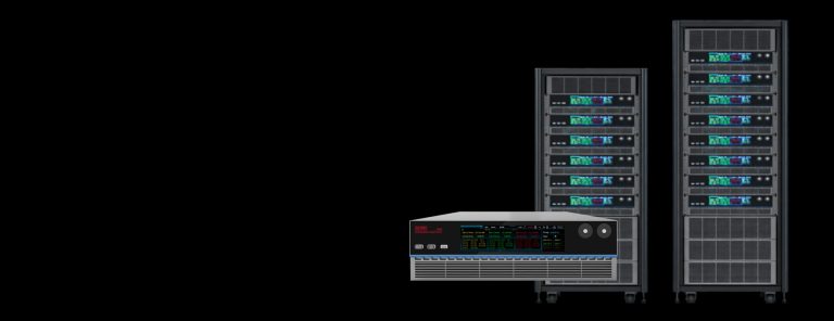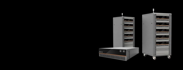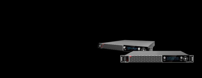
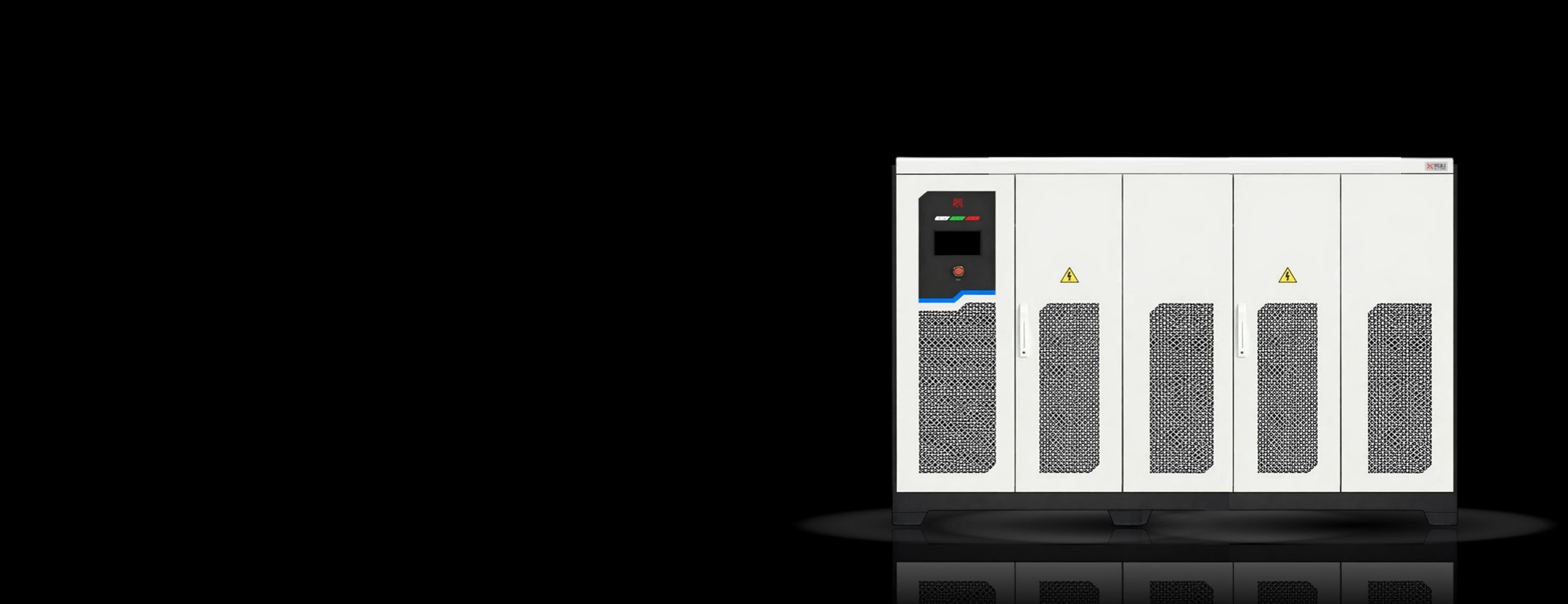
Meet the unprecedented high-power testing platform of TITAN for grid interoperability requirements validation as per IEEE 1541 and UL 1741, applicable for grid-forming inverters and PCS, V2G systems, wind turbine inverters and energy storage systems - the ultimate AC emulator featuring high-power, dynamics, response, flexible testing sequence automation, and proven by industrial leading certification institutes including TÜV SÜD & Intertek.
Detailed installation, operation procedures, and safety information for engineers.
Technical specification that provides full detailed introduction to TITAN AC emulator.
| Model | Power (kVA) | Voltage Range (V) | Frequency (Hz) | Max. Current (A) | Dimension (mm) | Weight (kg) |
|---|---|---|---|---|---|---|
| TA1K0-450-16L | 1000 | 0-450 | 40-70 | 1600 | 8410x1955x1400 | 8720 |
| TA1K0-700-10L | 1000 | 0-700 | 40-70 | 1000 | 4410x1955x1400 | 6610 |
| TA1K0-860-10L | 1000 | 0-860 | 40-70 | 1000 | 4410x1955x1400 | 6610 |
| TA300-450-05L | 300 | 0-450 | 40-70 | 500 | 2910x1955x1200 | 2930 |
| TA300-700-03L | 300 | 0-700 | 40-70 | 300 | 2910x1955x1200 | 2860 |
| TA300-860-03L | 300 | 0-860 | 40-70 | 300 | 2910x1955x1200 | 2860 |
| TA400-450-06L | 400 | 0-450 | 40-70 | 600 | 2910x1955x1200 | 3220 |
| TA400-700-04L | 400 | 0-700 | 40-70 | 400 | 2910x1955x1200 | 3040 |
| TA400-860-04L | 400 | 0-860 | 40-70 | 400 | 2910x1955x1200 | 3040 |
| TA500-450-08L | 500 | 0-450 | 40-70 | 800 | 4210x1955x1400 | 4360 |
| TA500-700-05L | 500 | 0-700 | 40-70 | 500 | 2910x1955x1200 | 3260 |
| TA500-860-05L | 500 | 0-860 | 40-70 | 500 | 2910x1955x1200 | 3260 |
| TA600-450-09L | 600 | 0-450 | 40-70 | 900 | 4410x1955x1400 | 4910 |
| TA600-700-06L | 600 | 0-700 | 40-70 | 600 | 4210x1955x1200 | 4170 |
| TA600-860-06L | 600 | 0-860 | 40-70 | 600 | 4210x1955x1200 | 4170 |
| TA750-450-12L | 750 | 0-450 | 40-70 | 1200 | 4410x1955x1400 | 6160 |
| TA750-700-07L | 750 | 0-700 | 40-70 | 700 | 4210x1955x1400 | 5880 |
| TA750-860-07L | 750 | 0-860 | 40-70 | 700 | 4210x1955x1400 | 5880 |
Advanced high-power AC emulator with SCR and X/R configuration capability, integrated RLC-modelling and anti-islanding test modes, user-controlled weak grid condition emulation and pre-compliace test sequence automation as per IEEE and UL standards.
Integrating AC source and AC load functioning into a single unit, TITAN AC Emulator is a bidirectional and full four-quadrant test platform with regenerative technology when operating as load mode for feeding back energy to local utility instead of dissipating as heat, with an outstanding efficiency of up to 94%.
The bidirectional grid interaction capability reduces laboratory HVAC and thermal management cost, while flexibly handling test and validation application regarding grid interoperability, TITAN functions as an ideal test platform for high-intensity, long-duration utility-scale validation and performance validation of grid-forming inverters, high-power energy storage systems and PCS, as well as large-capability UPS or BBU in HVDC AI data center.
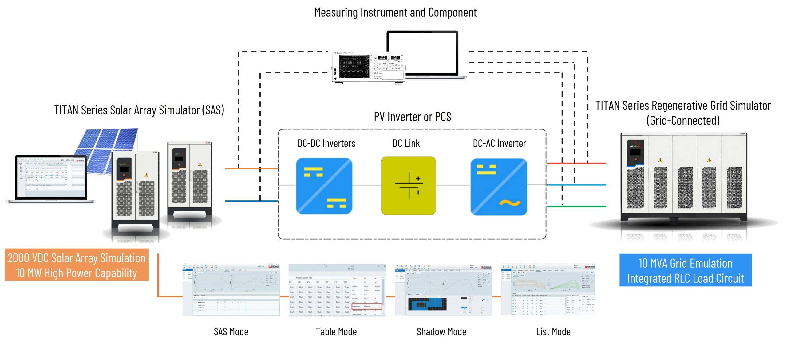
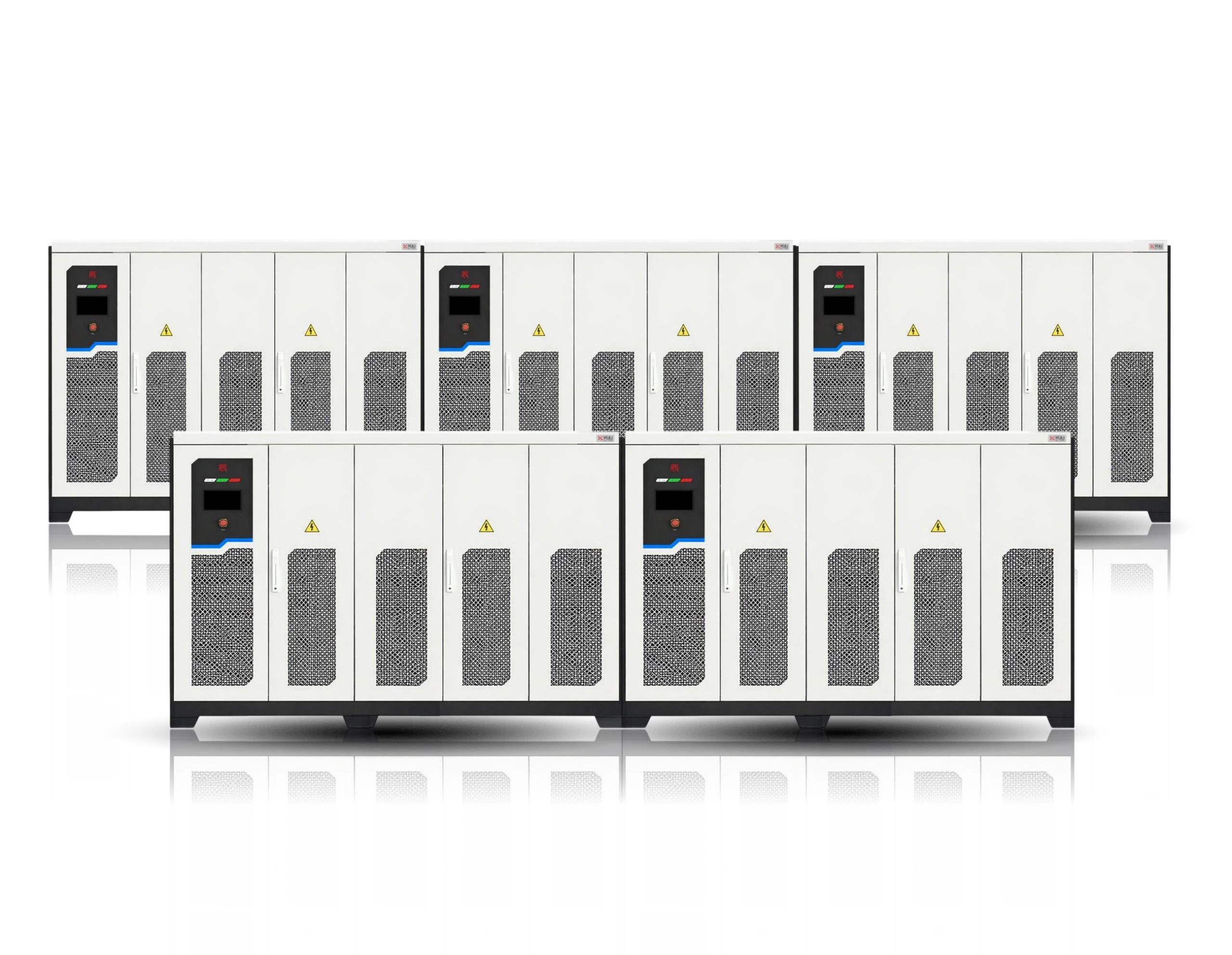
While a single set of AC emulator reaches the maximum power of 1MVA, it works as a the fundamental building block for configuring your utility-scale grid code compliance test platform through DMPS technology to reach as maximum as 10MVA power rating, without latency or compromised performance and dynamics.
For users such as certification institutes where requirements and demands are shifting, platform reconfiguration is allowed among the parallelled matrix for splitting a single 10MVA platform in to several subsidiary master-slave systems for multi-output and multi-station testing application setup, without the essentialness of a whole system replacement.
Confronting the latest challenges in grid-forming capabilities as per those testing guidelines specified in IEEE 1547.1-2020 following the update of IEEE 1547-2018 where requirements are proposed for grid-supporting capability of DERs. TITAN AC emulator addresses these challenges with an integrated FPGA-based RLC modelling for achieving independently and dynamically adjustment of Resistance (R), Inductance (L), and Capacitance (C) parameters in real-time - to replicate complex grid conditions and handle applications such as anti-islanding test without engaging additional RLC load banks.
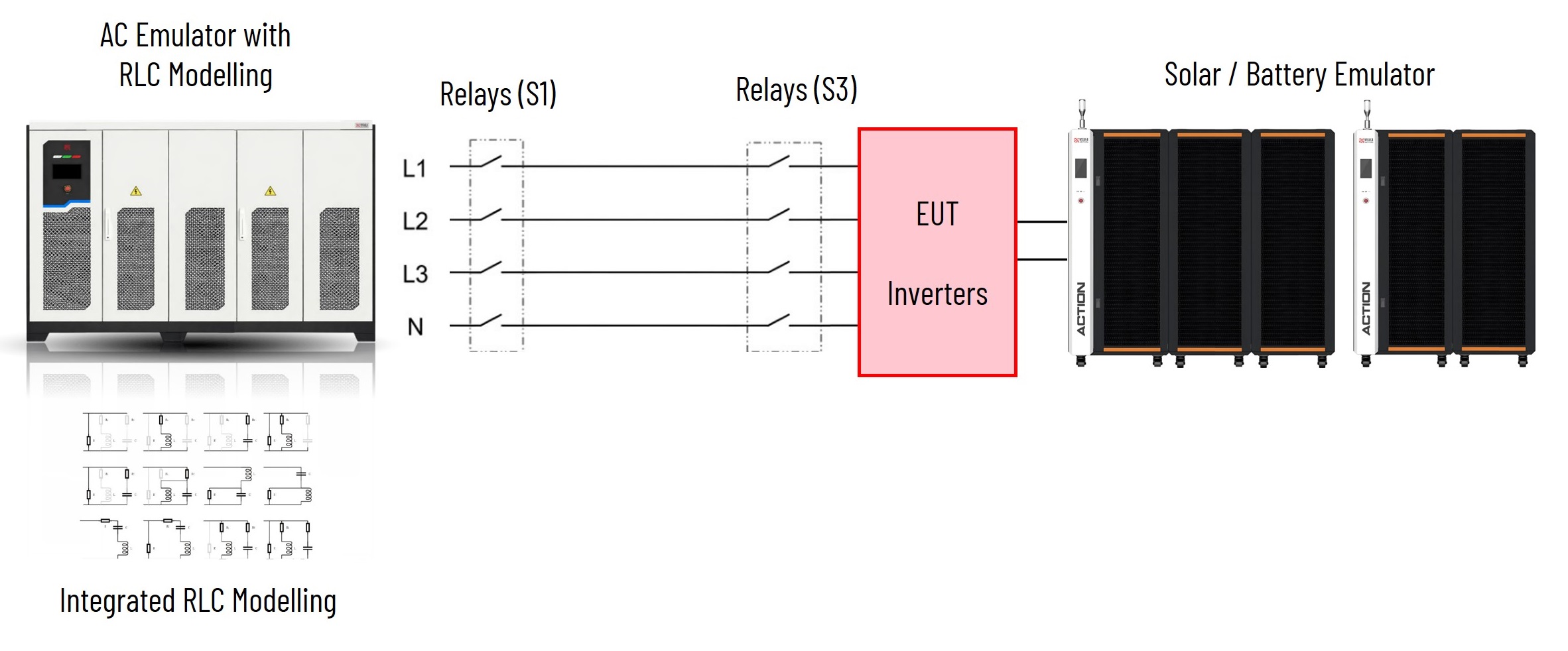
When conducting grid-tied equipment testing with TITAN AC emulator, engineers can configure the Short Circuit Ratio (SCR) and impedance angle (X/R ratio) via the software interface for simulating the specific impedance characteristics of any grid node. The R&D teams may efficiently verify control loop stability and harmonic oscillation suppression under severe conditions, such as extreme grid impedance fluctuations and ultra-low SCR environments.
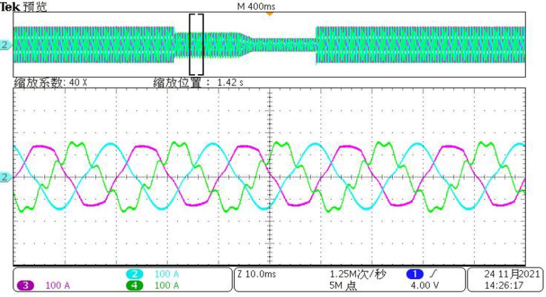
Targeting the most stringent international distributed energy grid-tied standards, TITAN delivers ready-to-use, pre-compliance-grade testing capabilities. Standards like IEEE 1547.1 2020 and UL 1741 SB demand highly sophisticated grid-support functions from smart inverters (e.g., Volt-VAR, Volt-Watt, Frequency-Watt, ROCOF, etc.). Test engineers no longer has to set up the testing application sequence and do programming from scratch, go-to-market process is accelerated with reduced opportunity cost, your saving and potential earning are achieved with an pre-compliance integrated software.
The following specifications are subject to modifications and changes without notification in advance. All specifications measured are at product's maximum ratings, if not otherwise noted.
| VOLTAGE | |
|---|---|
| Voltage Resolution (V) | 0.01 |
| Accuracy | ±0.1% F.S. |
| Waveform Types | Sine |
| DC Component (mV) | < 50 |
| Voltage Distortion |
< 0.5% @ 50Hz/60Hz, ≥220V no load; linear load < 1% < 1.0% @ 40Hz–70Hz, ≥220V no load; linear load < 1.5% |
| Load Regulation | ±0.1% F.S. |
| Line Regulation | ±0.1% F.S. @ 10% variation |
| Voltage Slew Rate | AC > 1.0 V/μs |
| Dynamic Response | < 1 ms (10%–90% Umax) |
| Three-phase Unbalance | Does not exceed half the limit specified in GB/T 15543-2008 (negative sequence voltage ≤1%, short-term ≤2%) |
| FREQUENCY | |
|---|---|
| Setting Resolution | 0.001 |
| Precision | ±0.01% or 0.005Hz |
| PHASE SETTING | |
|---|---|
| Setting Range | A=0°, B=240°, C=120°; Independent setting for each phase between 0°-359.9° |
| Precision | ±0.3° |
| Setting Resolution | 0.1° |
| HARMONICS | |
|---|---|
| Harmonic Orders | 50 orders @ 50Hz, 50 orders @ 60Hz, below rated voltage |
| Harmonic Content |
2–10th: max 40% per order, total ≤ 40% 11–20th: max 20% per order, total ≤ 20% 21–30th: max 10% per order, total ≤ 10% 31–50th: max 5% per order, total ≤ 5% |
| Amplitude Error | ±5% of harmonic content setting (orders ≤ 25) |
| Phase Angle Range | 0° ~ 359.9° |
| Preview Function | Preview of harmonic superimposed waveform available |
| Edit Mode | Import, export, load, and save supported |
| OUTPUT VOLTAGE | |
|---|---|
| Resolution(V_rms) | |
| Precision | ±0.1%F.S. |
| OUTPUT FREQUENCY | |
|---|---|
| Resolution(V_rms) | 0.01 |
| Precision | ±0.01% |
| OUTPUT CURRENT | |
|---|---|
| Resolution(A) | 0.001 |
| Precision | ±0.2%F.S. |
| ACTIVE POWER | |
|---|---|
| Resolution(W) | 0.1 |
| Precision | ±0.3%F.S. |
| APPARENT POWER | |
|---|---|
| Resolution(VA) | 1 |
| Precision | ±0.3%F.S. |
| POWER FACTOR | |
|---|---|
| Range | -1.00 ~ +1.00 |
| Resolution | 0.001 |
| INTER-HARMONICS | |
|---|---|
| Frequency Range | 1Hz ~ 3000Hz, content < 10% |
| Programming Steps | 100 steps |
| Programmable Parameters | Content, start frequency, end frequency, step size, execution time, interval time, number of cycles |
| Edit Mode | Add, delete, import, export, store, and load |
| FLICKERS | |
|---|---|
| Flicker Levels | 1.0 ~ 10.0, 10 levels in total, one-click selection |
| Adjustment Step Size | ±0.2 |
| Accuracy | ±0.2 |
| Preview Function | Flicker trend chart preview available |
| Three-Phase Voltage Unbalance Simulation | |
|---|---|
| Adjustment Parameters | Three-phase voltage, phase angle; unbalance factor |
| Unbalance Factor Adjustment Range (%) | 1 ~ 100, one-click selection |
| Unbalance Factor Step Size (%) | ±0.5% |
| Accuracy (%) | ±0.5% |
| LVRT / HVRT | |
|---|---|
| Mode 2 | |
| Configuration Parameters | Voltage, frequency, phase, rise time, hold time, trigger phase angle, trigger pulse output |
| Related Functions | Low voltage ride-through (LVRT) / high voltage ride-through (HVRT) / combined high & low voltage ride-through |
| Standards Compliance | Complies with GB (China National Standards), VDE-AR-N 4105, NRS 097-2-1, G83, EN50438, and others |
| PROGRAMMING | |
|---|---|
| Programming Steps | 100 steps |
| Parameters per Step | Voltage, frequency, phase, rise time, hold time, trigger phase angle, trigger pulse output |
| Rise Time Range | 100 μs ~ 999 s |
| Hold Time Range | 100 μs ~ 999 s |
| Minimum Time Step | 100 μs |
| Sync Signal Output |
One electrically isolated low-voltage trigger signal synchronized with output parameter changes. Supports single step, single loop, and single trigger modes (pulse or level selectable). |
| Edit Mode | Import, export, store, and load |
| Related Functions | Three-phase unbalance, voltage sag, interruption, LVRT/HVRT, with automation integration interface |
| Operating Modes | Run, stop, nested programming with main and sub loops |
| Trigger Methods | Automatic, manual, or external |
| Wiring Method | Three-phase four-wire ABC + PE |
|---|---|
| Frequency (Hz) | 47 ~ 63 |
| Voltage Range (V) | 380 ±15% |
| Power Factor | 0.99 @ above half load |
| Efficiency | >94% |
| Current Harmonics | <3% |
| Communication Interface | Standard: LAN; Optional: RS485, CAN |
|---|---|
| External Interlock | Input: Normally Open/Normally Closed; Output: Normally Open/Normally Closed |
| Trigger Signal | Trigger input/output |
| Insulation & Withstand Voltage | 10 MΩ / DC 500V; 3600 VAC / 1 min |
| Control & Display | Local touchscreen control, remote PC control; displays voltage, current, frequency, and power |
| Cooling Method | Forced air cooling |
| Noise | <70 dB |
| LINEAR LOAD | |
|---|---|
| Constant Current Mode | Load type, current slope, output waveform; parameters: current, power factor, linear load |
| Constant Power Mode | Apparent power, power factor, load type, power slope, output waveform |
| Constant Resistance Mode | Resistance value |
| RLC Mode |
RLC connection types: R+L+C, R//L//C, (R//C)+L, (R+L)//C, (R+C)//L Configurable parameters: resistance, inductance, capacitance |
| Nonlinear Load | Supported |
| Zero Voltage Start |
Parameters: current, power, crest factor, current slope, power slope Simulates load startup from zero voltage; after startup, seamless switching to constant current or constant power modes based on user-defined conditions |
| VOLTAGE | |
|---|---|
| Allowed Voltage Distortion Limit | UTHD < 10% for harmonic orders below the 20th |
| CURRENT | |
|---|---|
| Current Resolution (A) | 0.01 |
| Accuracy (A) | ±0.2% F.S. @ constant current mode |
| Waveforms | Sine, square, triangle, clipped, custom waveform |
| Current Distortion | <2% @ 50Hz at rated voltage and full load |
| Current Slew Rate | 10% ~ 90% of rated current > 1 A/μs |
| Dynamic Response | <1 ms @ 10% ~ 90% of rated current |
| FREQUENCY | |
|---|---|
| Range (Hz) | 40.00~70.0 |
| Precision | ±0.01Hz |
| HARMONICS | |
|---|---|
| Harmonic Orders | Up to 50 orders |
| Limits for 2nd–10th Orders | Max 40% per order; total harmonic content ≤ 40% |
| Limits for 11th–20th Orders | Max 20% per order; total harmonic content ≤ 20% |
| Limits for 21st–30th Orders | Max 10% per order; total harmonic content ≤ 10% |
| Limits for 31st–50th Orders | Max 5% per order; total harmonic content ≤ 5% |
| Phase Angle per Order | 0° ~ 359.9° |
| POWER | |
|---|---|
| Power Setting Resolution (VA) | 0.01 |
| Accuracy (VA) | ±0.5% F.S. @ constant power mode |
| POWER FACTOR | |
|---|---|
| Power Factor Range | -1 ~ +1 (supports inductive/resistive/capacitive settings; current direction configurable) |
| Crest Factor Setting Range | 1.414 ~ 4 |
| CREST FACTOR | |
|---|---|
| Crest Factor Resolution | 0.001 |
| Programming Steps | 100 steps |
| LIST PROGRAMMING | |
|---|---|
| Supported Modes | Constant current, constant power |
| Programmable Parameters |
Current/power, power factor, load type, rise time, hold time, trigger phase angle, trigger pulse output |
| Rise Time Range | 100 μs ~ 999 s |
| Hold Time Range | 100 μs ~ 999 s |
| Minimum Time Step | 100 μs |
| Sync Signal Output |
One electrically isolated low-voltage trigger signal, synchronized with output parameter changes; supports single-step, single-loop, and single-trigger (pulse or level selectable) |
| Edit Mode | Add, delete, store, and load |
| Operating Modes | Run, stop, nested programming with main and sub loops |
| Trigger Methods | Automatic, manual, or external |
| AC VOLTAGE | |
|---|---|
| Resolution(V) | 0.01 |
| Accuracy | ±0.1%F.S. |
| OUTPUT FREQUENCY | |
|---|---|
| Resolution(Hz) | 0.001 |
| Accuracy | ±0.01Hz |
| AC CURRENT | |
|---|---|
| Resolution(A) | 0.1 |
| Accuracy | ±0.2%F.S. |
| ACTIVE POWER | |
|---|---|
| Resolution(W) | 1 |
| Accuracy | ±0.5%F.S. |
| APPARENT POWER | |
|---|---|
| Resolution(VA) | 1 |
| Accuracy | ±0.5%F.S. |
| POWER FACTOR | |
|---|---|
| Range | -1.00 ~ +1.00 |
| Resolution | 0.001 |
| CREST FACTOR | |
|---|---|
| Range | 1.414~4 |
| Resolution | 0.001 |
| Wiring Method | Three-phase four-wire ABC + PE |
|---|---|
| Frequency (Hz) | 47 ~ 63 |
| Voltage Range (V) | 380 ±15% |
| Power Factor | 0.99 @ above half load |
| Efficiency | >94% |
| Current Harmonics | <3% |
| Communication Interface | Standard: LAN; Optional: RS485, CAN |
|---|---|
| External Interlock | Input: Normally Open/Normally Closed; Output: Normally Open/Normally Closed |
| Trigger Signal | Trigger input/output |
| Insulation & Withstand Voltage | 10 MΩ / DC 500V; 3600 VAC / 1 min |
| Control & Display | Local touchscreen control, remote PC control; displays voltage, current, frequency, and power |
| Cooling Method | Forced air cooling |
| Noise | <70 dB |
ActionPower India is a regional network of Xi'an ActionPower Electric Co., Ltd., represented by Tangent Test Technologies in India for supporting business development and technical services for our regional clientele in the field of power testing. With 5 regional locations in India.
With 30 years of experience with power electronics and testing solutions, further backed by 295+ patents that enforce our technological advancement, we are ready to uncomplicate your challenges of industrial regulation compliance with IEC, IEEE, UL and India local grid code standards.