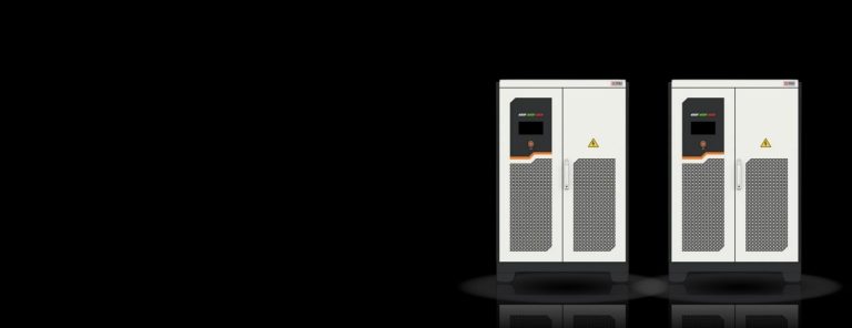
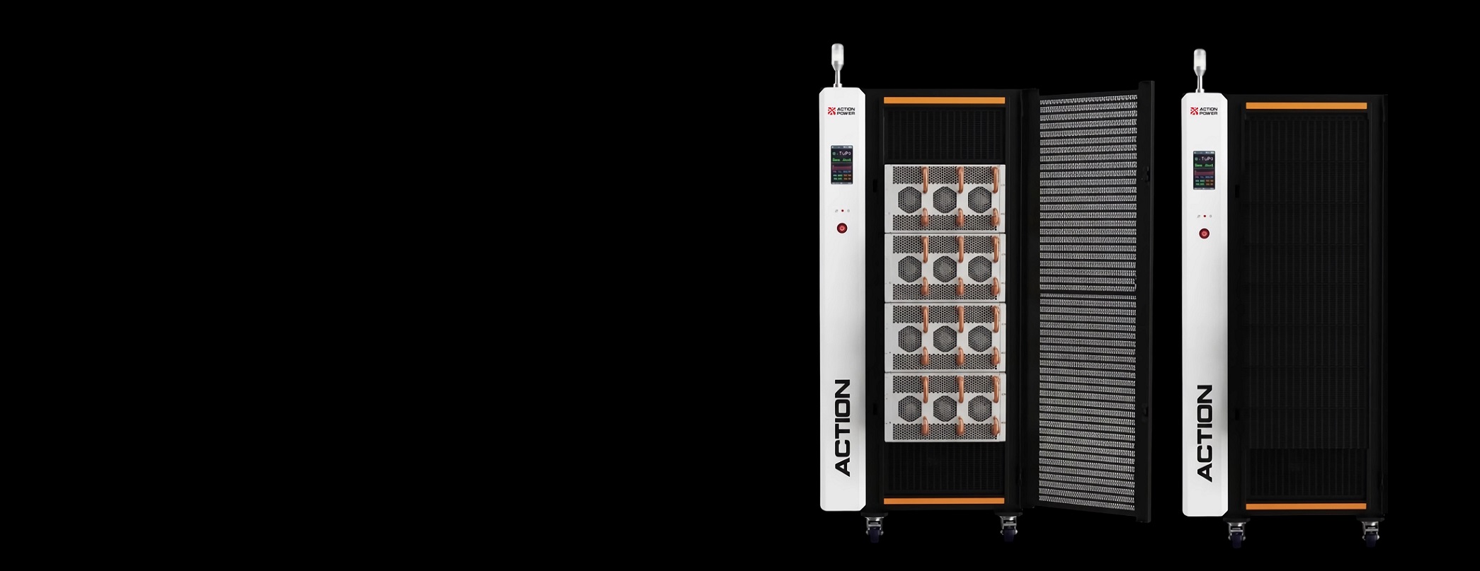
NEXUS DC is an integrated testing system with programmable source and load functions. Powerful programming capability and smart software additionally refine the system optionally into bidirectional battery simulator, solar array simulator or a battery cycler for matching versatile testing application use cases. Modular scalable architecture scales up from 50 kW towards 750 kW from a single unit and reaches to 6 MW as maximum power with 8 units of cabinet in parallel connection.
Detailed installation, operation procedures, and safety information for engineers about NEXUS Series DC Source-Load Simulator.
| Model | Power (kW) | Output Voltage (V) | Output Current (A) | Dimensions (mm) W × H × D | Weight (kg) |
|---|---|---|---|---|---|
| PRO20-D05-2201 | ±50 | 20–2250 | ±100 | 800x1000x1950 | 465 |
| PRO20-D10-2202 | ±100 | 20–2250 | ±200 | 800x1000x1950 | 465 |
| PRO20-D15-2203 | ±150 | 20–2250 | ±300 | 800x1000x1950 | 590 |
| PRO20-D20-2204 | ±200 | 20–2250 | ±400 | 800x1000x1950 | 590 |
| PRO20-D25-2205 | ±250 | 20–2250 | ±500 | 800x1000x1950 | 715 |
| PRO20-D30-2206 | ±300 | 20–2250 | ±600 | 800x1000x1950 | 715 |
| PRO20-D35-2207 | ±350 | 20–2250 | ±700 | 800x1000x1950 | 840 |
| PRO20-D40-2208 | ±400 | 20–2250 | ±800 | 800x1000x1950 | 840 |
| PRO20-D45-2209 | ±450 | 20–2250 | ±900 | 1400x1000x1950 | 1245 |
| PRO20-D50-2210 | ±500 | 20–2250 | ±1000 | 1400x1000x1950 | 1245 |
| PRO20-D55-2211 | ±550 | 20–2250 | ±1100 | 1400x1000x1950 | 1370 |
| PRO20-D60-2212 | ±600 | 20–2250 | ±1200 | 1400x1000x1950 | 1370 |
| PRO20-D65-2213 | ±650 | 20–2250 | ±1300 | 1400x1000x1950 | 1495 |
| PRO20-D70-2214 | ±700 | 20–2250 | ±1400 | 1400x1000x1950 | 495 |
| PRO20-D75-2215 | ±750 | 20–2250 | ±1500 | 1400x1000x1950 | 1620 |
| PRO20-D80-2216 | ±800 | 20–2250 | ±1600 | 1400x1000x1950 | 1620 |
High-power, flexible-architecture, versatile DC source-load simulator, with functions around battery simulation, PV simulation and battery cycling test applications.
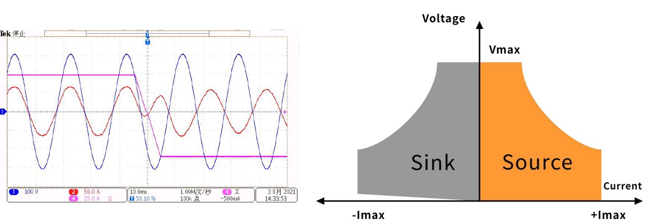
NEXUS Source-Load Simulator is nature a bidirectional programmable DC power supply that automatically sets its operation mode among the sourcing and load power with zero latency or overshoot. When applied for DC load simulation such as for dynamics testing simulating AI server in HVDC testing scenarios, NEXUS feeds energy back to utility grid with a 95% energy efficiency for saving your energy testing cost.
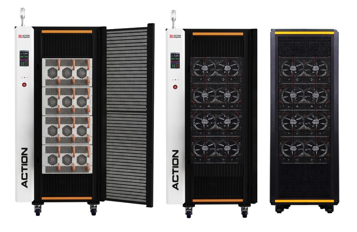
NEXUS DC simulator is architected based on 50 kW power modules and scales up to 750 kW from a single cabinet from only a compact footprint of 1400*1000 mm, equivalent to a high power density of 563 kW per m2. Inter-cabinet scalability allows 8 units of cabinet to be connected in parallel as master-slave system with a maximum power of 6 MW.
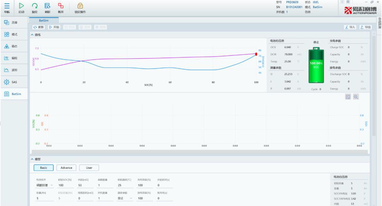
With bidirectionality and battery emulation capability, NEXUS DC source-load simulator replicates the charging and discharging behaviours with built-in operation profiles and chemistry characteristic models covering lithium manganese oxide (LMO), lithium iron phosphate (LiFePO4), ternary lithium, and lead-acid, along with fully opens up 1st-order, 2nd-order, and even 3rd-order RC battery model reconfiguration capabilities.
User-defined settings are available with customizable series/parallel configurations, initial SOC, internal resistance, cell capacity adjustments, and CSV format importing, supported by an ultra-fast command update rate of 200 µs.
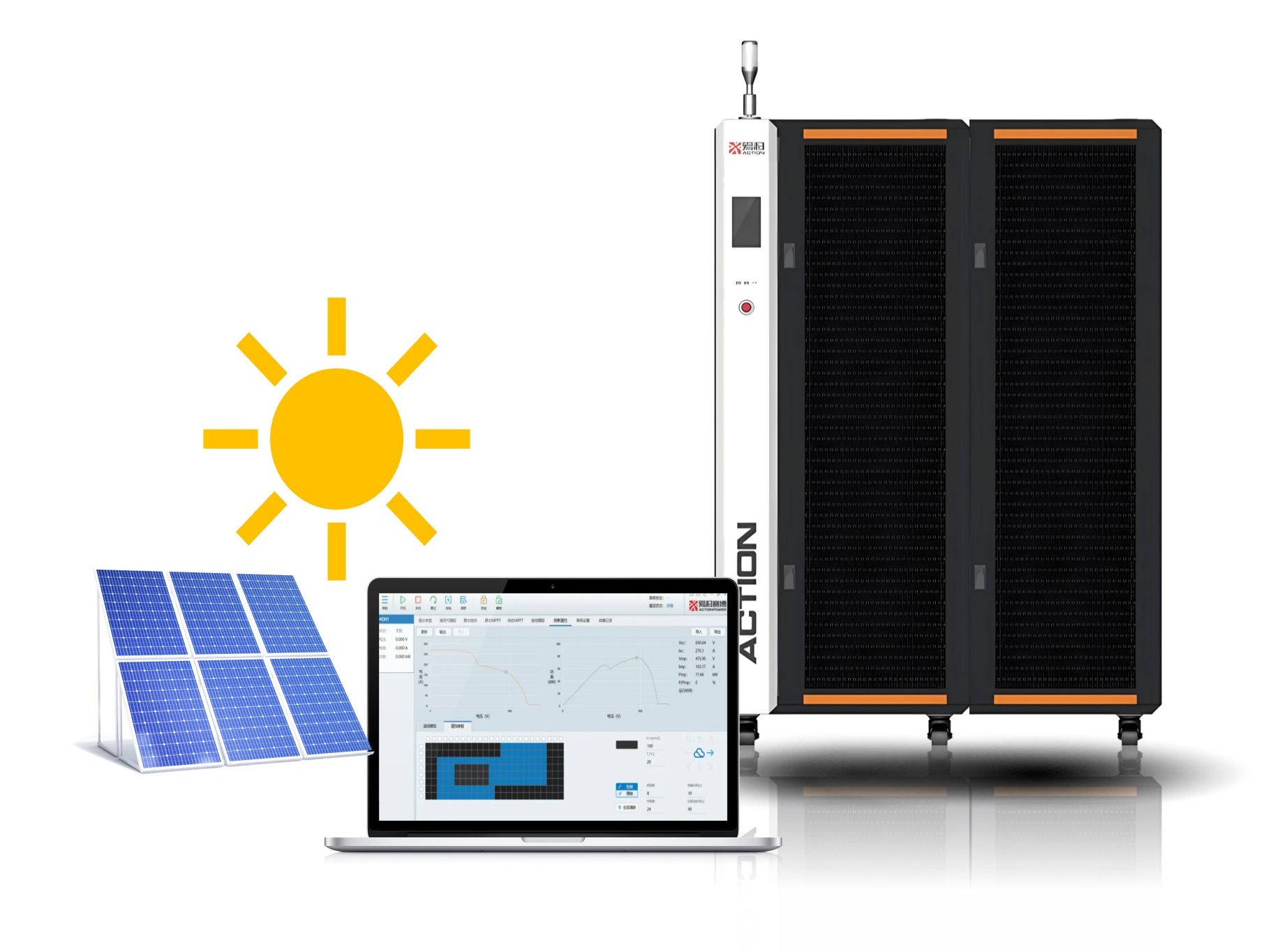
NEXUS DC source-load simulator supports 4,096 points high-resolution I-V curve plotting for MPPT testing against PV inverter following international PV protocol models such as EN 50530 and Sandia. Quick test setup for static and dynamic MPPT tracking is further supported by additional injection of unideal external natural conditions such as cloudy whether and partial shading.
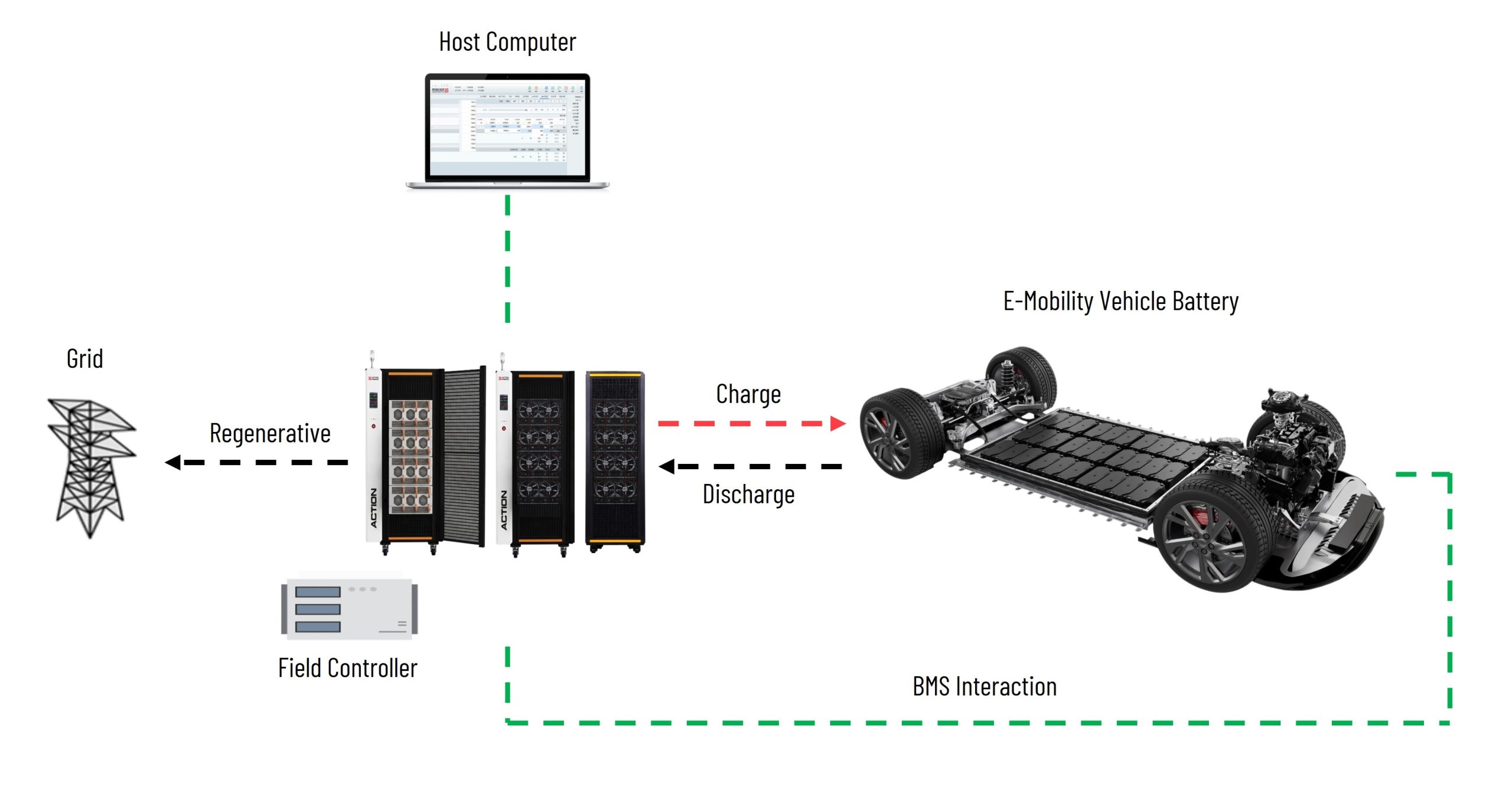
High dynamics and ultra-fast-response of NEXUS DC source-load simulator that achieves microsecond recovery for full-load switching provide the functionality foundation for battery cycling and life cycle test against utility-scale energy storage battery and EV battery pack. ActionPower India's team is proficient in developing the software that applies for such use cases for converting NEXUS DC into a high-performance battery cycler ATE.
Note: The following specifications are subject to modifications and changes without notification in advance. All specifications measured are at product's maximum ratings, if not otherwise noted.
| Voltage Range (V) | 304VAC ~ 456VAC |
|---|---|
| Frequency (Hz) | 47-63Hz |
| Wiring Code | 3pH+PE |
| Efficiency | ≥95% |
| Power Factor | ≥0.99 |
| Programming Accuracy | ±(0.05% Setting + 0.05% F.S.) |
|---|---|
| Programming Resolution | ±0.01 A |
| Readback Accuracy | ±(0.05% Reading + 0.05% F.S.) |
| Readback Resolution | ±0.001 A |
| Source Regulation | +0.1% F.S. |
| Load Regulation | ±0.1% F.S. |
| Rise Time (10~90% F.S.) | < 1 ms |
| Transition Time (-90~90% F.S.) | < 2 ms |
| Programming Accuracy | ±(0.1% Setting + 0.1% F.S.) |
|---|---|
| Programming Resolution | ±1 W |
| Readback Accuracy | ±(0.1% Reading + 0.1% F.S.) |
| Readback Resolution | ±1 W |
| Range | Refer to User Manual |
|---|---|
| Programming Accuracy | ±(0.1% Setting + 0.2% F.S.) @ ≥3% of rated current |
| Programming Resolution | 0.012 |
| Readback Accuracy | ±(0.1% Setting + 0.2% F.S.) @ ≥3% of rated current |
| Readback Resolution | 0.010 |
| Programming Modes | List, Wave, Step, Advanced |
|---|---|
| Programming Steps | Up to 200 steps |
| Loop Count Range | 0 ~ 9,999,999 times |
| Time Range | 0 ms ~ 999 s |
| Minimum Time Step | 100 μs |
| Edit Functions | Add, Delete, Import, Export |
| Execution Modes | Load, End, Trigger |
| Communication Interfaces | Standard: USB, LAN; Optional: RS485, CAN |
|---|---|
| Multi-Function Interface | "Anyport" (refer to User Manual for detailed definition) |
| Operating Temperature | -10 ~ 50 °C (derating above 35 °C) |
|---|---|
| Storage Temperature | -20 ~ 70 °C |
| Humidity | ≤80% (non-condensing) |
| Altitude | ≤2000 m |
| Programming Accuracy | ±(0.05% Setting + 0.05% F.S.) |
|---|---|
| Programming Resolution | ±0.1 V |
| Readback Accuracy | ±(0.05% Reading + 0.05% F.S.) |
| Readback Resolution | ±0.01 V |
| Source Regulation | ±0.05% F.S. @ 10% change |
| Load Regulation | ±0.05% F.S. |
| Remote Sense Compensation | Max. Voltage and 2% F.S. ±1 V |
| Rise Time | < 1 ms (10~90% F.S.) |
| Dynamic Overshoot | ±5% F.S. |
| Recovery Time | < 1.5 ms to settle within ±0.75% F.S. after 50% to 100% or 100% to 50% load step |
| Voltage Ripple (RMS) | 1 V |
| Slew Rate Range (No Load) | 1000 V/ms |
| Slew Rate Range (Full Load) | 500 V/ms |
| Voltage Accuracy | ±0.1% F.S. |
|---|---|
| Voltage Resolution (V) | 0.01 |
| Current Accuracy | ±0.1% F.S. |
| Current Resolution (A) | 0.01 |
| Power Accuracy | ±(0.1% Reading + 0.1% F.S.) |
| Power Resolution (kW) | 0.01 |
| Battery Types | Supports simulation of lithium manganate, lithium cobalt oxide, lithium iron phosphate, nickel-metal hydride, ternary lithium, lithium titanate, lead-acid, and other chemistries; customizable battery types with open 1st, 2nd, and 3rd order RC models |
|---|---|
| Configurable Parameters | Series/parallel cell count, initial SOC, initial temperature, internal resistance, cell capacity, etc.; supports CSV import for customized models |
| Interface | Standard communication and control interfaces |
| Real-Time Performance | 200 μs command update rate |
| Open-Circuit Voltage Setting Range | Full voltage range configurable |
|---|---|
| Short-Circuit Current Setting Range | 0 A ~ Ie |
| Fill Factor Simulation Range | 0.3 ~ 0.95 |
| PV Module Type Selection | c-Si, Thin-film, Custom |
| I-V Curve Update Rate | Typical 1 ms, with online curve switching capability |
| I-V Curve Standards | EN50530, Sandia, Simple |
| I-V Curve Functions | Static curve, curve scanning, static sequence, static MPPT, dynamic MPPT, weather simulation, shading simulation, curve programming, custom curves |
| Curve Configuration |
1) Customizable by Voc, Isc, FF, Pm and other parameters 2) Dynamic operating mode considers environmental effects such as temperature and irradiance, continuously outputting I-V curves under varying conditions 3) Built-in EN50530 / Sandia dynamic I-V test procedures |
| Protection Functions | Input over-voltage / under-voltage / over-frequency / under-frequency / phase loss; Output over-voltage / over-current / over-power; Internal over-temperature protection |
|---|---|
| Control & Display | Local touchscreen control, remote PC control; Display of voltage, current, power, and operating trend curves |
| Cooling Method | Forced air cooling |
| Insulation (Negative to PE) | 3400 VDC |
| Insulation (Positive to PE) | 3400 VDC |
| Insulation (Input to PE) | 3100 VDC |
ActionPower India is a regional network of Xi'an ActionPower Electric Co., Ltd., represented by Tangent Test Technologies in India for supporting business development and technical services for our regional clientele in the field of power testing. With 5 regional locations in India.
With 30 years of experience with power electronics and testing solutions, further backed by 295+ patents that enforce our technological advancement, we are ready to uncomplicate your challenges of industrial regulation compliance with IEC, IEEE, UL and India local grid code standards.