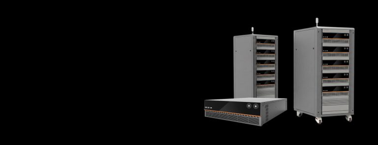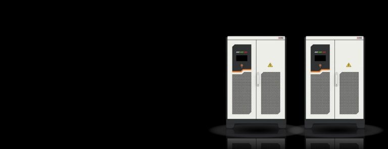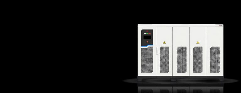
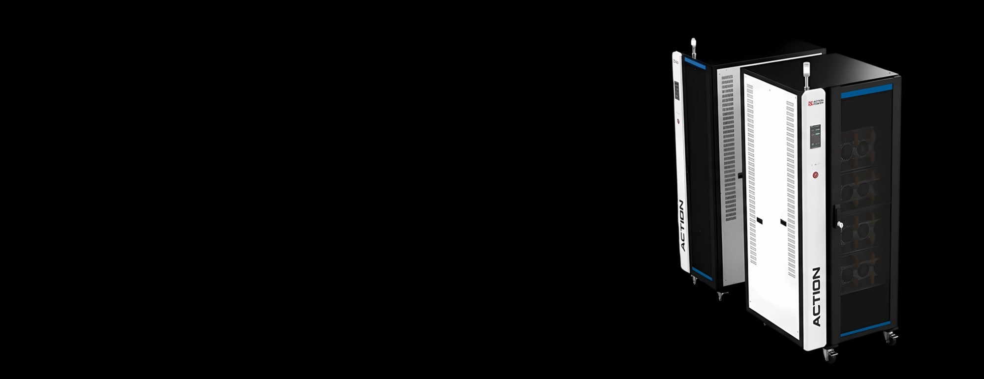
Achieving compatibility between high-power and flexibility, NEXUS modular scalable grid simulator covers your grid interconnection test application crossing power-level from component to utility-scale systems. With fundamental scaling block unit of 50 kVA, a single cabinet of NEXUS can contain 8 modules for reaching 400 kVA and further by integrating a slave cabinet containing 7 modules for reaching 750 kVA with a single standalone system and 8 units to be connected in parallel for reaching 6 MVA maximum power rating. Versatile grid emulation functions available from the control interface and through host control with advanced software of Action 2020 developed by ActionPower.
Detailed installation, operation procedures, and safety information for engineers about NEXUS Series Grid Simulator.
| Model | Power (kVA) | Output Voltage (V) | Output Current (A) | Dimensions (mm) W × H × D |
|---|---|---|---|---|
| PRO20-60-4712 | ±600 | 0.001–200.0 | ±1200 | 1400x1000x1950 |
| PRO20-A10-4702 | ±100 | 0.001–200.0 | ±200 | 800x1000x1950 |
| PRO20-A10-9001 | ±100 | 0.001–200.0 | ±100 | 800x1000x1950 |
| PRO20-A20-4704 | ±200 | 0.001–200.0 | ±400 | 800x1000x1950 |
| PRO20-A20-9002 | ±200 | 0.001–200.0 | ±200 | 800x1000x1950 |
| PRO20-A30-4706 | ±300 | 0.001–200.0 | ±600 | 800x1000x1950 |
| PRO20-A30-9003 | ±300 | 0.001–200.0 | ±300 | 800x1000x1950 |
| PRO20-A40-4708 | ±400 | 0.001–200.0 | ±800 | 800x1000x1950 |
| PRO20-A40-9004 | ±400 | 0.001–200.0 | ±400 | 800x1000x1950 |
| PRO20-A50-4710 | ±500 | 0.001–200.0 | ±1000 | 1400x1000x1950 |
| PRO20-A50-9005 | ±500 | 0.001–200.0 | ±500 | 400x1000x1950 |
| PRO20-A60-9006 | ±600 | 0.001–200.0 | ±600 | 1400x1000x1950 |
| PRO20-A70-4714 | ±700 | 0.001–200.0 | ±1400 | 1400x1000x1950 |
| PRO20-A70-9007 | ±700 | 0.001–200.0 | ±700 | 1400x1000x1950 |
| PRO20-A75-4715 | ±750 | 0.001–200.0 | ±1500 | 1400x1000x1950 |
Modular scalable system for grid interoperability testing with compatibility around high power, flexibility and programmability and phased scalable testing system management.
Power module integrated within NEXUS are powered by ActionPower's patented power electronics technology. NEXUS achieves 750 kVA from a single cabinet through fiber-based communication without the slightest latency. The system supports phased scalability from 50 kW to 6 MVA with a maximum 8 units of cabinet in parallel connection. The compact footprint together with high-power rating supports with a maximum density of 563 kVA per m2.
Redundancy feature is available among, in case of a 6 MVA platform, the 56 power modules aligned throughout the 6 MVA grid code test platform for safeguarding consistent operation without downtime for testing automation.
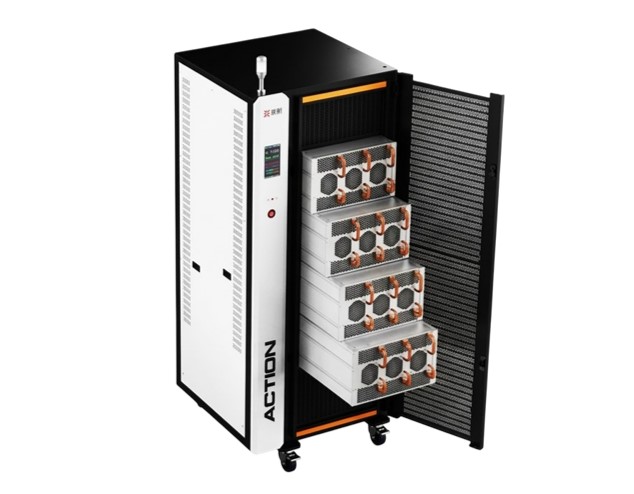
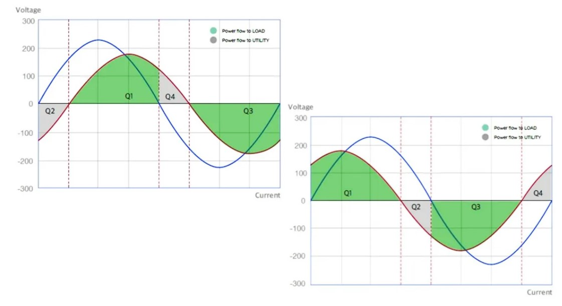
NEXUS modular-scalable grid simulator is an integrated source-load and four-quadrant system (additionally with AC, DC, AC+DC output capability) with regenerative load functionality when operating as a programmable load for grid interconnection test. A load operation, standard CC, CP, CR and PQ are supporting for load emulation while recovering 92.5% of the energy back to utility. The system save your energy cost during power testing, relief your thermal management stress and HVAC implementation cost.
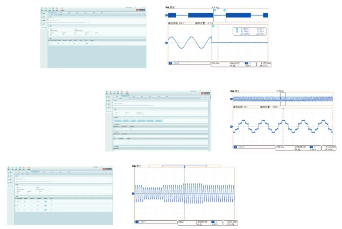
With the optimization technology combining algorithm and hardware foundations, NEXUS offers a high current precision of ±(0.1%+0.1% F.S.) for operation between 15~200 Hz. High slew rate demonstrates the excellent dynamics of NEXUS, reaching the fastest slew rate of 1.5V/μs and with capability of replicating 90° transient voltage shift or 100μs voltage dips validation.
Versatile user-defined programming capability allows List, Wave, Step and Pulse, Advanced modes, along with 100 sets of custom waveform available for test engineer to set up complex test sequence automation with harmonics, inter-harmonics, sags and other transient conditions.
NEXUS is both at operation and at system-level ready for validating (PV) inverters and Power Conversion Systems (PCS) against complex grid interaction conditions through an integrated 12 options of RLC modelling for replicating complex linear and non-linear load simulation.
NEXUS integrates multiple complex models, including 2-pulse to 24-pulse, positive/negative half-wave, and leading/trailing edge half-wave. Coupled with a broad Crest Factor (CF) setting range of 1 to 6, realistically replicating the impedance characteristics of various residential and industrial non-linear electrical terminals.

NEXUS supports weak grid condition emulation thanks to its high-precision control, RLC network along with user-definable customized setting of Short Circuit Ratio (SCR) and X/R ratio characteristics.
Weak grid emulation supports the replication of utility conditions at the terminals of long-distance transmission lines or in remote microgrids in laboratory with purpose of verifying the grid-tied control stability (grid-forming capability) and anti-islanding protection performance of distributed energy resources (DERs) under grid impedance fluctuations.

NEXUS is specifically developed for grid code compliance testing with a comprehensive set of built-in pre-compliance testing automation sequence in alignment with both regional and international grid code standards and interoperability regulations. Test engineer no longer has to program by themselves for the applicable standards and testing guidelines yet may select from the built-in recipes including UL 1741, IEEE 1547.1, IEC 62116, IEC 61000-4 series along with regional applicable testing requirements. The system accelerates your to-market process and save your enduring in-house programming process along with the subsequent opportunity cost.
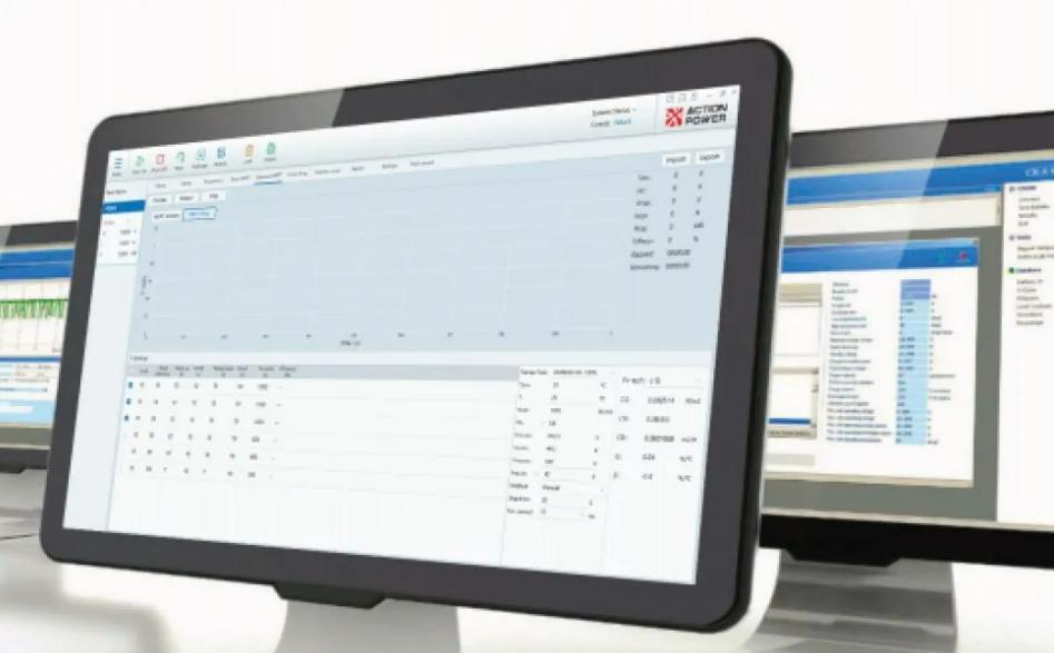
Note: The following specifications are subject to modifications and changes without notification in advance. All specifications measured are at product's maximum ratings, if not otherwise noted.
| Output Modes | AC, DC, AC+DC, DC+AC |
|---|---|
| Operation Modes | Bidirectional & Regenerative |
| Output Phase Options | 3-Phase, Split-Phase, Single-Phase |
| RESISTANCE | |
|---|---|
| Range (Ω) | 0.001 – 1000 |
| Setting Resolution (Ω) | 0.001 |
| Accuracy | ±0.1% F.S. |
| INDUCTANCE | |
| Range (mH) | 1 – 5000 |
| Setting Resolution (mH) | 0.001 |
| Accuracy | ±0.1% F.S. |
| CAPACITANCE | |
| Range (µF) | 1 – 5000 |
| Setting Resolution (µF) | 0.001 |
| Accuracy | ±0.1% F.S. |
| CREST FACTOR | |
| Range | 1.000 – 5.000 |
| Resolution | 0.001 |
| POWER FACTOR | |
| Range | 1.000 – 1.000 |
| Resolution | 0.001 |
| VOLTAGE | |
|---|---|
| Setting Resolution (V) | 0.01V |
| Output Accuracy | ±(0.01% + 0.05% F.S.) |
| Output Ripple (V_rms) |
|
| Load Regulation | ±0.05% F.S. |
| Line Regulation | ±0.01% F.S. @ 10% variation |
| Output Slew Rate |
|
| CURRENT | |
| Setting Resolution | 0.01 |
| Accuracy | ±(0.1% + 0.1% F.S.) |
| Voltage Accuracy | ±(0.05% + 0.05% F.S.) |
|---|---|
| Current Accuracy | ±(0.1% + 0.2% F.S.) |
| Active Power Accuracy | ±0.5% F.S. |
| Apparent Power Accuracy | ±0.5% F.S. |
| Connection Method | Three-phase four-wire ABC + PE |
|---|---|
| Frequency (Hz) | 47 – 63 |
| Voltage Range (V) | 304 – 456 |
| Power Factor | ≥ 0.99 @ rated power |
| Efficiency | ≥ 94% |
| Communication Interface | USB, LAN, RS485 (optional) |
|---|---|
| Multi-function Interface | "Anyport", details defined in user manual |
| Operating Temperature | -10°C to +50°C |
| Altitude | ≤ 2000 m |
| Relative Humidity | 10% to 80% RH |
| Protection Functions | Input overvoltage/undervoltage/overfrequency/underfrequency/phase loss protection; Output overvoltage/overcurrent/ overpower protection; Internal overtemperature protection |
| Control & Display | Local touch screen operation, remote PC control; displays voltage, current, frequency, power |
| Cooling Method | Forced air cooling |
| Insulation (Negative–PE) | 3400 VDC |
| Insulation (Positive–PE) | 3400 VDC |
| Insulation (Input–PE) | 3100 VDC |
| VOLTAGE | |
|---|---|
| Setting Resolution | 0.01 V |
| Accuracy | ±(0.05% + 0.05% F.S.) |
| Waveform Types | Sine, Triangle, Pulse, Clipped Wave, Half-Wave, Multi-Pulse, 30 DST Groups, Custom Waveform |
| DC Component (mV) | < 50 mV (DC component) |
| Voltage Distortion |
|
| Load Regulation | ±0.05% F.S. (Line Regulation) |
| Line Regulation | ±0.05% F.S. @ 10% variation |
| Remote Sense | Adaptive (Remote Sense) |
| Voltage Slew Rate |
|
| Three-Phase Unbalance | Not exceeding 1/2 of the GB/T15543-2008 requirement (Negative-sequence voltage ≤1%, short-term ≤2%) |
| FREQUENCY | |
| Range (Hz) | DC, 0.001–200.0 |
| Setting Resolution (Hz) | 0.001 |
| Accuracy | 0.01% |
| PHASE | |
| Range | A = 0°, B = 240°, C = 120° (default); Programmable range 0°–359.9°, three phases independently adjustable |
| Accuracy | ±0.1° @ 15–70 Hz; ±0.5° @ 70–200 Hz |
| Setting Resolution | ±0.1° @ 15–70 Hz; ±0.5° @ 70–200 Hz |
| HARMONICS | |
| Orders | Up to 100 orders @ 40–70 Hz, 25 orders @ 70–200 Hz |
| Content | Maximum 40% per order, total content up to 40% |
| Phase Angle Range | 0°–359.9° |
| Amplitude Error | ±5% or 0.1% of the fundamental value |
| Preview Function | Preview of waveform with harmonic superposition |
| Edit Mode | Import, Export, Read, Store |
| CURRENT | |
| Impulse RMS (A_rms) | 1.1 times rated for continuous operation, 1.2 times rated for up to 20 s |
| Setting Resolution (A) | 0.01 |
| Crest Factor | 1–6 |
| Accuracy | 0.1% + 0.1% F.S. @ 15–200 Hz |
| PROGRAMMING | |
| Programming Modes | List, Wave, Step, Pulse, Advanced, Harmonic, Interharmonic |
| Minimum Programming Time Step | 100 μs |
| Number of Steps | 100 steps |
| Trigger Source | Local software, external hardware |
| Loop Count | 0–9,999,999 |
| Parameters per Step | Voltage, Frequency, Phase, Ramp Time, Dwell Time, Trigger Phase Angle, Trigger Pulse Output |
| Ramp Time Range | 100 μs – 999 s |
| Dwell Time Range | 100 μs – 999 s |
| Trigger Output & Enable | One isolated low-voltage trigger signal, synchronized with power output parameter changes; supports single step, single cycle, single pulse triggering |
| Edit Mode | Import, Export, Store, Read |
| Run Mode | Run, Stop, Large loop (9,999,999) + Nested small loop (9,999,999) |
| Trigger Mode | Automatic, Manual, External |
| FREQUENCY MODULATION | |
| Source Mode | Supported Modes |
| Programming Steps | 100 steps |
| Programming Parameters | Modulation Amplitude, Modulation Frequency, Dwell Time, Trigger Phase Angle |
| Programming Mode | Import, Export, Store, Read |
| Trigger Source | Local Software, External Hardware |
| Trigger Mode | Automatic, Single Step |
| AMPLITUDE MODULATION | |
| Supported Modes | Source Mode |
| Programming Steps | 100 steps |
| Programming Parameters | Modulation Amplitude, Modulation Frequency, Dwell Time, Trigger Phase Angle |
| Programming Mode | Import, Export, Store, Read |
| Trigger Source | Local Software, External Hardware |
| Trigger Mode | Automatic, Single Step |
| Control Method | Percentage, Absolute Value |
| INTERNAL-RESISTANCE MODE | |
| R Range (Ω) | 0–10 (under steady-state output impedance) |
| L Range (mH) | 0–2 |
| Setting Resolution | 0.001 |
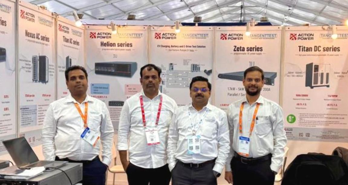
ActionPower India is a regional network of Xi'an ActionPower Electric Co., Ltd., represented by Tangent Test Technologies in India for supporting business development and technical services for our regional clientele in the field of power testing. With 5 regional locations in India.
With 30 years of experience with power electronics and testing solutions, further backed by 295+ patents that enforce our technological advancement, we are ready to uncomplicate your challenges of industrial regulation compliance with IEC, IEEE, UL and India local grid code standards.