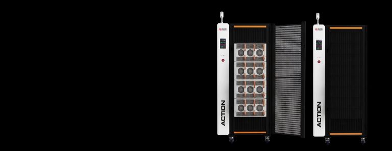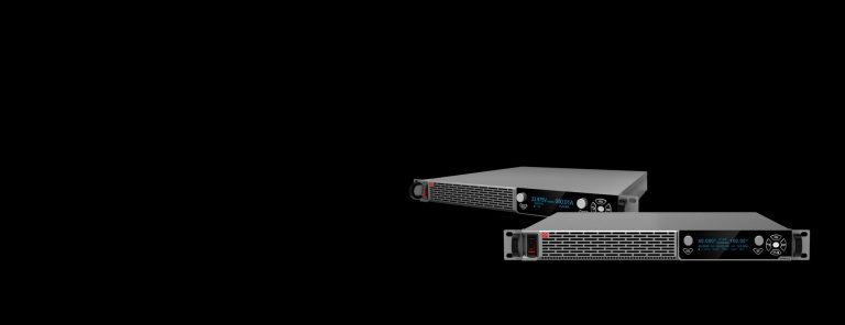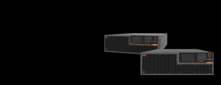
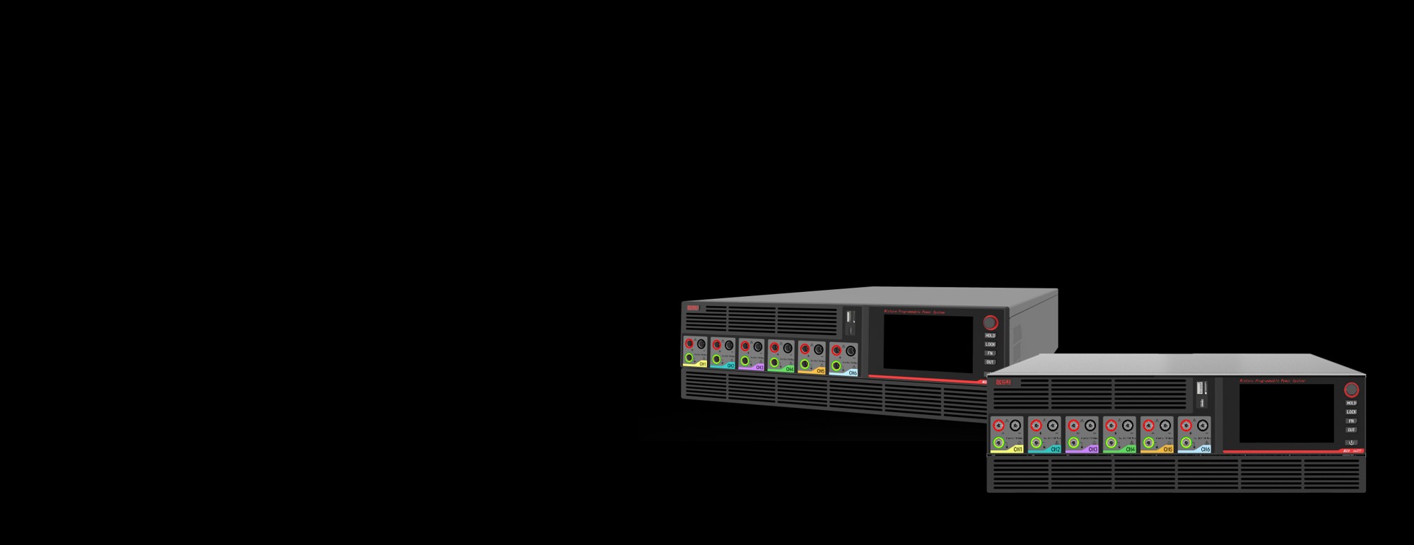
HELION multi-channel programmable power supply re-defines the flexibility of test bench. The 3U standard chassis incorporates 6 slots that allow plug-and-play modular test sequence setup with arbitrary combination and automatic identification of AC and DC modules - both with bidirectional energy flow capability. Diverse advanced emulation capability are available with HELION's power module for emulating PV (photovoltaic), battery or grid interaction. Additionally complemented by Web-based remote monitoring, HELION sets up within the compact footprint of 3U a flexible combo of testing options for microinverters, portable energy storage, and industrial power electronics.
Technical specification that provides full detailed introduction to HELION Series Multi-Channel Programmable Power Supply

| Models | Rated Output Power (kW) | Input Voltage Range (V) | Channels | Input Type | Size |
|---|---|---|---|---|---|
| H-C6-6.6 | 6.6 | L1-N: (200-240)Vac L1-L2: (200-440)Vac |
6 | Two-wire | 3U Standard Unit |
| H-C6-9.9 | 9.9 | 200-480V | 6 | Three-phase | 3U Standard Unit |
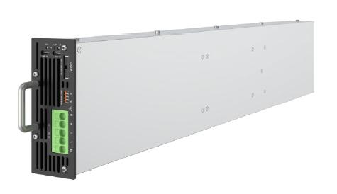
| Models | Power (kVA) | Max. Voltage (V_rms) | Frequency Range (Hz) | Maximum Current (A_rms) | Maximum Voltage (V_DC) | Maximum Current (A_DC) |
|---|---|---|---|---|---|---|
| A1-1.6-450-16 | 1.6 | 450 | DC, 0.001‒5000 | 16 | ±630 | ±16 |
| A1-3.0-450-16 | 3 | 450 | DC, 0.001‒5000 | 16 | ±630 | ±16 |
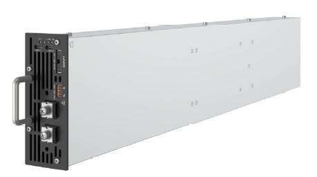
| Models | Rated Power (kW) | Voltage (V) | Current Rating (A) | Maximum Efficiency | Type |
|---|---|---|---|---|---|
| D1-0.8-100-30 | ±0.85 | 0-100 | ±30 | 90% | Bidirectional DC Module |
| D1-0.8-160-15 | ±0.85 | 0-160 | ±15 | 90% | Bidirectional DC Module |
| D1-1.6-100-45 | ±1.65 | 0-100 | ±45 | 90% | Bidirectional DC Module |
| D1-1.6-160-30 | ±1.65 | 0-160 | ±30 | 90% | Bidirectional DC Module |
| D1-3.0-100-60 | ±3.00 | 0-100 | ±60 | 92% | Bidirectional DC Module |
| D1-3.0-160-50 | ±3.00 | 0-160 | ±50 | 92% | Bidirectional DC Module |
| D2-0.8-100-30 | 0.85 | 0-100 | 30 | 90% | PV Simulation Module |
| D2-0.8-160-15 | 0.85 | 0-160 | 15 | 90% | PV Simulation Module |
| D2-1.6-100-45 | 1.65 | 0-100 | 45 | 90% | PV Simulation Module |
| D2-1.6-160-30 | 1.65 | 0-160 | 30 | 90% | PV Simulation Module |
Set up your own testing logic with the arbitrary combination of AC and DC power for either input and output, through 6 channels with flexible options of power modules. From a single 3U chassis HELION offers as maximum as 128 typse of power sequence combination.
From a compact 3U chassis of main-frame HELION fetches 9.9kW power meanwhile offering a maximum 6 independent channels into which power modules of AC and DC can be inserted for either sourcing or sinking power. The mounting approach based on module through hot-swapping, adaptive plug-and-play modular design, and 10A-current-supporting banana glue connectors significantly simplifies your R&D test bench setup in laboratory.

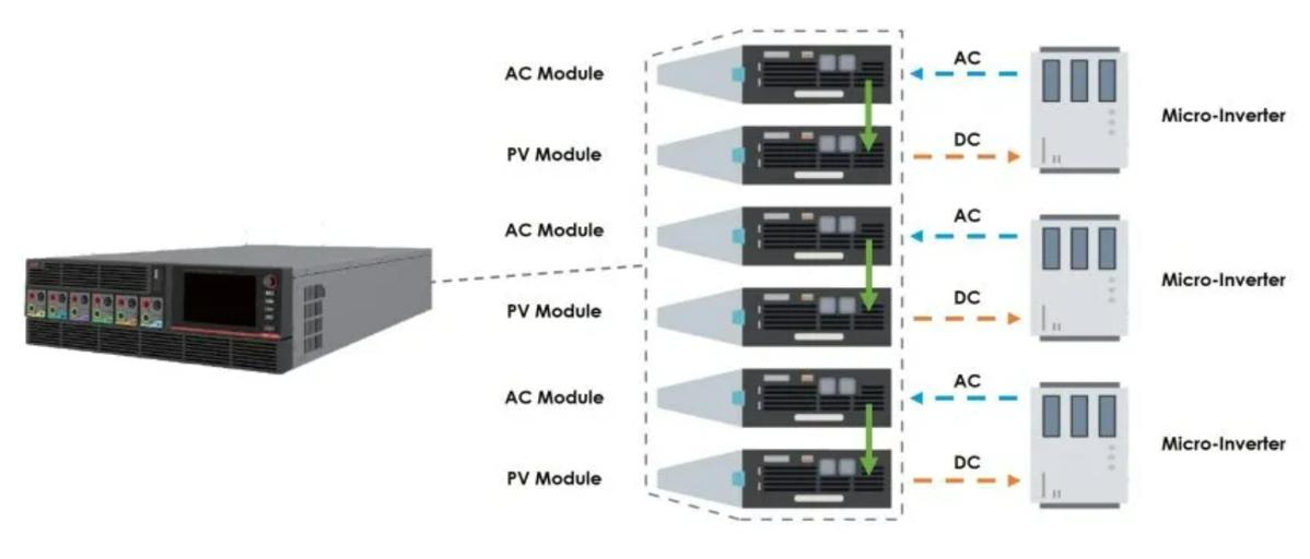
The flexible mixing and rapid replacement and combination of AC and DC modules paves your way to a flexible and versatile test bench setup with various complex testing topologies of AC/AC, AC/DC, DC/AC, and DC/DC, while both AC and DC modules within the system feature bidirectional energy flow. The 3U chassis achieves inter-module power flow and recycling and then feeds the power back to the utility grid for reducing facility power consumption and HVAC cooling cost,
Test data's trustworthiness relies on the reliability of the testing instrument. HELION integrates a precision measurement engine comparable to a 6.5-digit multimeter and demonstrates exceptional output and measurement accuracy (e.g., AC voltage accuracy up to 0.01%±0.05% F.S., and DC accuracy up to 0.02%±10mV).
Powered by advanced digital control technology, the device delivers ultra-low output ripple and noise alongside ultra-fast dynamic response speeds in the hundreds of microseconds, functioning a smooth, pure, and ultimate testing power source for highly sensitive loads.

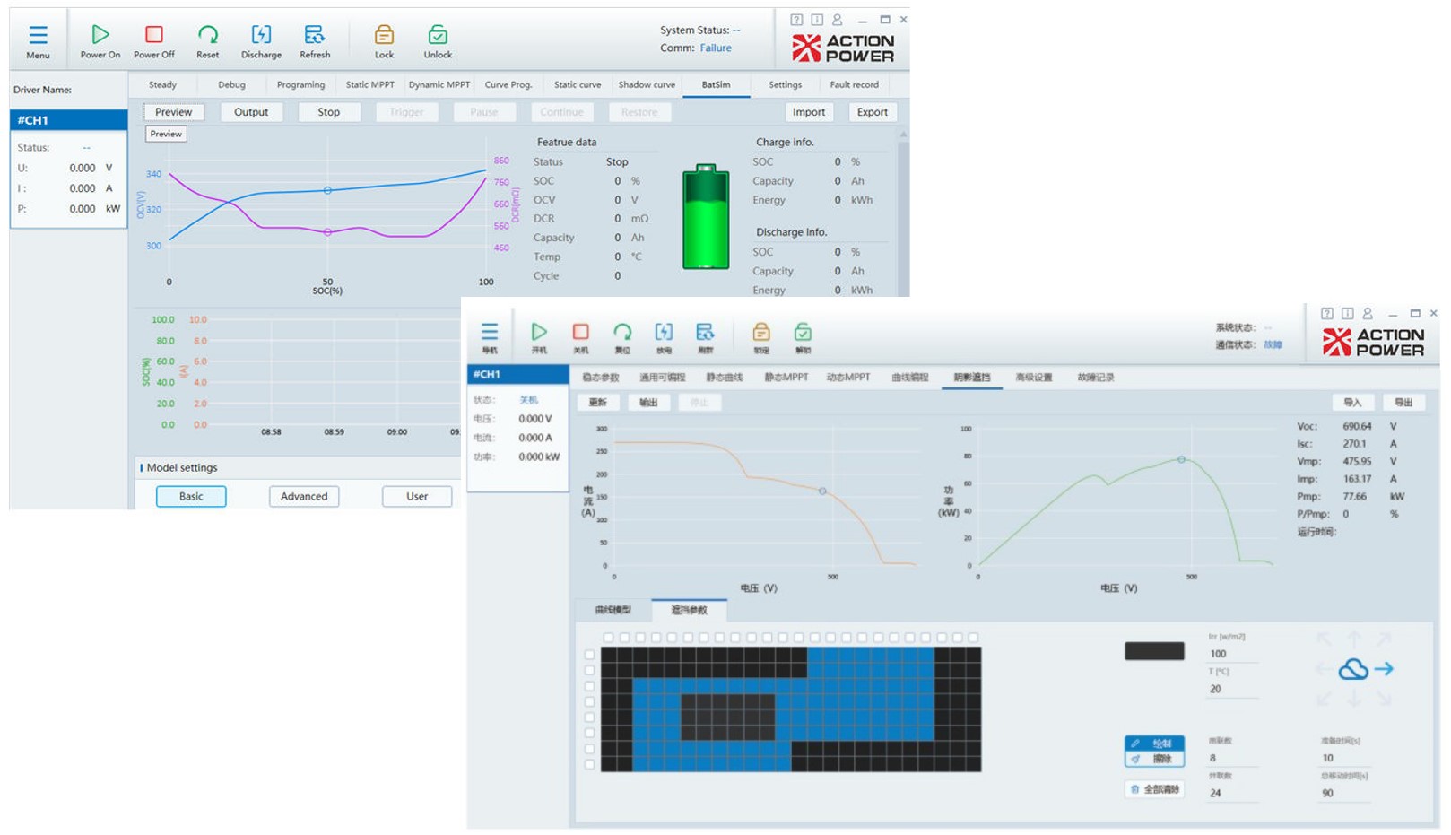
HELION integrates a powerful built-in specialized simulation software.
A battery emulation version of DC module replicate comprehensive battery chemistry characteristic covering mathematical models for lithium manganese, lithium iron phosphate, ternary lithium, and lead-acid batteries, with advanced settings of SOC and internal resistance available.
PV array (PV/SAS) simulation modules support static/dynamic MPPT testing, weather variation, and shadow simulation, with built-in international standard test curves such as EN50530.
Combined with its robust arbitrary waveform (List/Wave) editing and CSV data import functions, HELION replicates real-world, complex operating conditions.
HELION's 3U chassis integrates HD touch screen and physical rotary knobs for intuitive and efficient local operation. For advanced monitoring options, HELION offers a built-in Web server for test engineers to achieve comprehensive remote control and real-time monitoring via a standard LAN browser without the need to install any cumbersome PC software.
ATE system integration is available through multiple communication interfaces such as USB and LAN as standard options, and further compatibility is available with SCPI and MODBUS standard command sets.

Note: The technical parameters contained within the below specification tables are subject to updates and modifications without notification in advance. For more detailed technical information please contact our sales and technical support team.
| Wiring Type | MIX36300: 3ph+PE(L1/L2/L3+PE) |
|---|---|
| MIX36200: 2ph+PE(L1/L2+PE or L/N+PE) | |
| Rated Voltage | MIX36300: (200-440)VAC |
| MIX36200: L1-N:(200-240)VAC; L1-L2(200+440)VAC | |
| Rated Frequency | 50/60Hz |
| Frequency Range | 47-63Hz |
| Power Factor | 0.99 |
| Insulation Resistance | Input to PE | 500 VDC, > 30 MΩ (25°C, 70% RH) |
|---|---|---|
| Input to Output | 500 VDC, > 30 MΩ (25°C, 70% RH) | |
| Dielectric Strength | Input to Control Interface | 5kVAC |
| Input to Output | 3kVAC |
| Temperature | Operation | 0℃~50℃ |
|---|---|---|
| Storage | -20℃~70℃ | |
| Humidity | Operation | ≤80% Not condensing |
| Storage | ≤90% Not condensing | |
| Altitude | 2%/100m reduction in rated current when above 2000m | |
| Energy Internal Circulation | Total System Loss ≤ Mainframe System Distribution Power |
|---|---|
| Non-Energy Internal Circulation | Total Input Power ≤ Mainframe System Distribution Power |
| Maximum Number of Channels | 6 |
| Per-Channel Power Output | Max. 3kW |
| Control Interface | LAN: RJ45 connector; USB: Type-A USB 2.0, Type-C, Type-B; TF Card Slot; HDMI Output |
|---|
| Safety | IEC/EN 61010-1:2010 |
|---|---|
| Electromagnetic Compatibility | IEC/EN 61326-1:ClassA |
| Size | 435x132x750mm |
|---|---|
| Weight | 15kg |
| RMS Overcurrent Protection | Setting range: 0–110% F.S.; output is disconnected on overcurrent |
|---|---|
| Overpower Protection | Setting range: 0–110% F.S.; output is disconnected on overpower |
| Overcapacity Protection | Setting range: 0–110% F.S.; output is disconnected on overcapacity |
| DC Overvoltage Protection | Setting range: 0–110% F.S.; output is disconnected on overvoltage |
| AC Overvoltage Protection | Setting range: 0–110% F.S.; output is disconnected on overvoltage |
| Over/Under Frequency Protection | Setting range: 0.001 Hz – 5000.000 Hz; output is disconnected on frequency fault |
| Power Interface | Pluggable connectors |
|---|---|
| Control Interface | Remote sense connectors, ANYPORT port, parallel port, indicator lights |
| Safety | IEC/EN 61010-1:2010 |
|---|---|
| Electromagnetic Compatibility | IEC/EN 61326-1:ClassA |
| Operating Temperature | 0°C ~ 50°C (power derating above 40°C) |
|---|---|
| Storage Temperature | −20°C ~ 70°C |
| Operating Humidity | < 80%, non-condensing |
| Storage Humidity | < 90%, non-condensing |
| Altitude | Output current derates 2% per 100 m above 2000 m |
| Cooling Method | Forced air cooling (airflow directed toward rear panel) |
| Size | 127x665x50mm |
|---|---|
| Weight | ≤4.8kg |
| Setting Range | 160V output module: 0V~163.2V |
|---|---|
| 100V output module: 0V~120V | |
| Setting Accuracy① | ≤±(0.02% + 30 mV) |
| ≤±(0.02% + 20 mV) | |
| Setting Resolution | 10 mV |
| Line Regulation (±10% Uac) | ±0.01% F.S. |
| Load Regulation (0~100% Load) | ±0.02% F.S. |
| Recovery Time (10~90% Load Step)② | 0.8 ms |
| Rise Time (Full Load)③ | 10 ms |
| Rise Time (No Load)③ | 5 ms |
| Fall Time (Full Load)③ | 5 ms |
| Fall Time (No Load)③ | 10 ms |
| Ripple (Peak-to-Peak, 20 MHz)④ | 250 mVpp |
| Ripple (RMS, 300 kHz)④ | 40 mVrms |
| Remote Compensation | 160V output module: ≤6.0 V |
| 100V output module: ≤3.2 V |
| 160V Output Modules | 100V Output Modules | |
|---|---|---|
| Range | 0~192V | 0~120V |
| Resolution | 10mV | |
| Precision | ≤±(0.02%+30mV) | ≤±(0.02%+20mV) |
| 160V Output Modules | 100V Output Modules | |
|---|---|---|
| Range (3 kW Model) | 0~±60 A | 0~±72 A |
| Range (1.65 kW Model) | 0~±36 A | 0~±54 A |
| Range (0.85 kW Model) | 0~±18 A | 0~±36 A |
| Resolution | 1 mA | |
| Accuracy (3 kW Model) | ±(0.05% + 10 mA) | ±(0.05% + 10 mA) |
| Accuracy (1.65 kW Model) | ±(0.05% + 10 mA) | |
| Accuracy (0.85 kW Model) | ±(0.05% + 5 mA) | |
| Power Interface | Power copper bars with M5 screws; includes protective cover |
|---|---|
| Control Interface | Remote sense connector, ANYPORT port, parallel port, and status indicator lights |
| Operating Temperature | 0°C ~ 50°C (power derating above 40°C) |
|---|---|
| Storage Temperature | −20°C ~ 70°C |
| Operating Humidity | < 80%, non-condensing |
| Storage Humidity | < 90%, non-condensing |
| Altitude | Output current derates 2% per 100 m above 2000 m |
| Cooling Method | Forced air cooling (airflow directed toward rear panel) |
| 160V Output Modules | 100V Output Modules | |
|---|---|---|
| Setting Range (3 kW Model) | 0~±51 A | 0~±61.2 A |
| Setting Range (1.65 kW Model) | 0~±30.6 A | 0~±45.9 A |
| Setting Range (0.85 kW Model) | 0~±15.3 A | 0~±30.6 A |
| Setting Accuracy (3 kW Model)⑤ | ±(0.05% + 10 mA) | ±(0.05%+10mA) |
| Setting Accuracy (1.65 kW Model)⑤ | ±(0.05% + 10 mA) | |
| Setting Accuracy (0.85 kW Model)⑤ | ±(0.05% + 5 mA) | |
| Setting Resolution | 1 mA | |
| Line Regulation (±10% Uac) | ±0.02% F.S. | |
| Load Regulation (ΔU = 90% Uo) | ±0.02% F.S. | |
| Rise Time (10%~90% Rated Value)③ | 5 ms | |
| Fall Time (90%~–10% Rated Value)③ | 5 ms | |
| 160V Output Modules | 100V Output Modules | |
|---|---|---|
| Setting Range (3 kW Model) | 0~±3150 W | |
| Setting Range (1.65 kW Model) | 0~±1732.5 W | |
| Setting Range (0.85 kW Model) | 0~±892.5 W | |
| Setting Accuracy (3 kW Model) | ±0.2% F.S. | |
| Setting Accuracy (1.65 kW Model) | ±0.4% F.S. | |
| Setting Accuracy (0.85 kW Model) | ±0.6% F.S. | |
| Setting Resolution | 0.15 W | |
| Measurement Range (3 kW Model) | 0~±3600 W |
|---|---|
| Measurement Range (1.65 kW Model) | 0~±1980 W |
| Measurement Range (0.85 kW Model) | 0~±1020 W |
| Measurement Resolution | 0.15 W |
| Measurement Accuracy (3 kW Model) | ±0.2% F.S. |
| Measurement Accuracy (1.65 kW Model) | ±0.4% F.S. |
| Measurement Accuracy (0.85 kW Model) | ±0.6% F.S. |
| Digital Programming | Supported |
|---|---|
| Analog Programming | Supported |
| System Integration | Supports integration with external control systems |
| Voltage & Current Programming | Both voltage and current parameters can be programmed |
| Overcurrent Protection | Settable range: 0~110% F.S.; output shuts down when overcurrent occurs |
|---|---|
| Overpower Protection | Settable range: 0~110% F.S.; output shuts down when overpower occurs |
| Overvoltage Protection | Settable range: 0~110% F.S.; output shuts down when overvoltage occurs |
| Overtemperature Protection | Output shuts down when internal temperature exceeds the limit |
| Safety / EMC | IEC/EN 61010-1:2010 / IEC/EN 61326-1:ClassA |
|---|---|
| Size / Weight | 127x665x50mm / ≤5kg |
| 160V Output Module | 100V Output Module | |
|---|---|---|
| Setting Range | 0V~163.2V | 0V~102V |
| Setting Accuracy① | < ±(0.02% + 30mV) | < ±(0.02% + 20mV) |
| Setting Resolution | 10mV | |
| Line Regulation (±10% Uac) | ±0.01% F.S. | |
| Load Regulation (0~100% Load) | ±0.02% F.S. | |
| Recovery Time (10~90% Load Step)② | 0.8 ms | |
| Rise Time (Full Load)③ | 10 ms | |
| Rise Time (Without Load)③ | 5 ms | |
| Fall Time (Full Load)③ | 5 ms | |
| Fall Time (Without Load)③ | 10 ms | |
| Ripple Peak-to-Peak (20MHz)④ | 250 mVpp | |
| Ripple RMS (300kHz)④ | 40 mVrms | |
| Remote Sense Compensation | <6.0V | <3.2V |
| 160V Output Modules | 100V Output Modules | |
|---|---|---|
| Range | 0~192V | 0~120V |
| Resolution | 10mV | |
| Precision | ≤±(0.02%+30mV) | ≤±(0.02%+20mV) |
| 160V Output Modules | 100V Output Modules | |
|---|---|---|
| Range (3 kW Model) | 0~±60 A | 0~±72 A |
| Range (1.65 kW Model) | 0~±36 A | 0~±54 A |
| Range (0.85 kW Model) | 0~±18 A | 0~±36 A |
| Resolution | 1 mA | |
| Accuracy (3 kW Model) | ±(0.05% + 10 mA) | ±(0.05% + 10 mA) |
| Accuracy (1.65 kW Model) | ±(0.05% + 10 mA) | |
| Accuracy (0.85 kW Model) | ±(0.05% + 5 mA) | |
| Digital & Analog Programming | Supported |
|---|---|
| Voltage & Current Programming | Both voltage and current parameters can be programmed |
| Power Interface | Power copper bars with M5 screws; includes protective cover |
| Control Interface | Remote sense connector, ANYPORT port, parallel port, and status indicator lights |
| 160V Output Module | 100V Output Module | |
|---|---|---|
| Setting Range | 3kW Model: 0~51A | 3kW Model: 0~61.2A |
| 1.65kW Model: 0~30.6A | 1.65kW Model: 0~45.9A | |
| 0.85kW Model: 0~15.3A | 0.85kW Model: 0~30.6A | |
| Setting Accuracy⑤ | 3kW Model: ±(0.05% + 10mA) | 3kW Model: ±(0.05% + 10mA) |
| 1.65kW Model: ±(0.05% + 10mA) | ||
| 0.85kW Model: ±(0.05% + 5mA) | ||
| Setting Resolution | 1 mA | |
| Line Regulation (±10% Uac) | ±0.02% F.S. | |
| Load Regulation (AU = 90% Uo) | ±0.02% F.S. | |
| Rise Time (10%~90% rated) ③ | 5 ms | |
| Fall Time (90%~10% rated) ③ | 5 ms | |
| 160V Output Module | 100V Output Module | |
|---|---|---|
| Setting Range | >3kW Model: 0~3150W | |
| >1.65kW Model: 0~1732.5W | ||
| >0.85kW Model: 0~892.5W | ||
| Setting Accuracy | >3kW Model: ±0.2% F.S. | |
| >1.65kW Model: ±0.4% F.S. | ||
| >0.85kW Model: ±0.6% F.S. | ||
| Setting Resolution | >0.15 W | |
| Overcurrent Protection | Settable range: 0~110% F.S.; output shuts down when overcurrent occurs |
|---|---|
| Overpower Protection | Settable range: 0~110% F.S.; output shuts down when overpower occurs |
| Overvoltage Protection | Settable range: 0~110% F.S.; output shuts down when overvoltage occurs |
| Overtemperature Protection | Output shuts down when internal temperature exceeds the limit |
| Operating Temperature | 0°C ~ 50°C (power derating above 40°C) |
|---|---|
| Altitude | Output current derates 2% per 100 m above 2000 m |
| Safety / EMC | IEC/EN 61010-1:2010 / IEC/EN 61326-1:ClassA |
| Size / Weight | 127x665x50mm / ≤5kg |
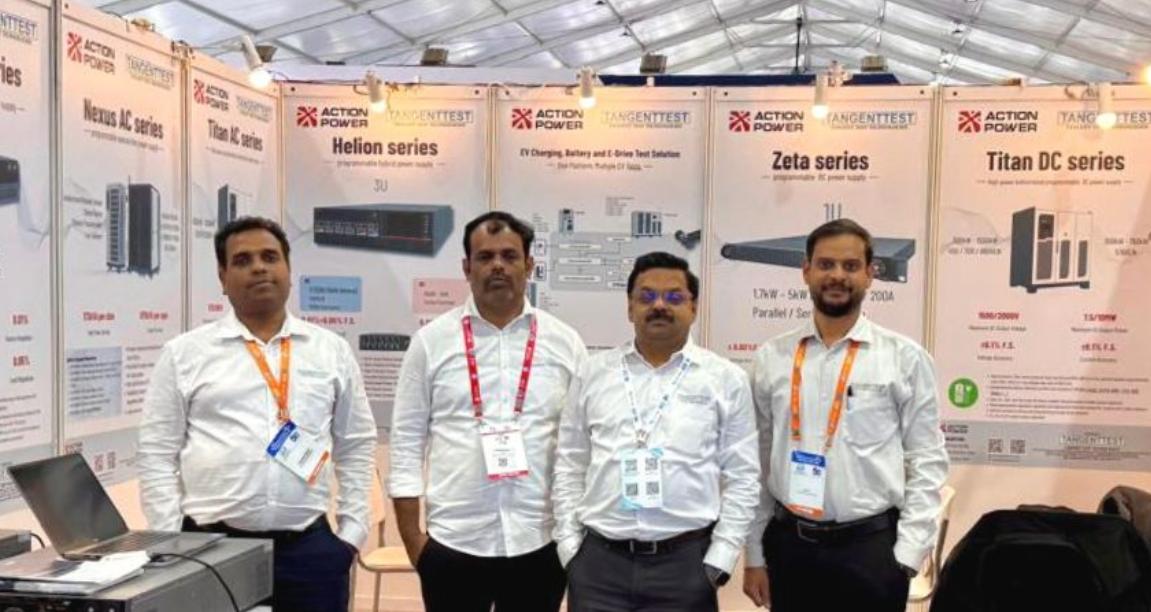
ActionPower India is a regional network of Xi'an ActionPower Electric Co., Ltd., represented by Tangent Test Technologies in India for supporting business development and technical services for our regional clientele in the field of power testing. With 5 regional locations in India.
With 30 years of experience with power electronics and testing solutions, further backed by 295+ patents that enforce our technological advancement, we are ready to uncomplicate your challenges of industrial regulation compliance with IEC, IEEE, UL and India local grid code standards.