Why Conventional Loads Demonstrates Better Dynamics Performance than Regenerative Ones? And How ActionPower India Breaks the Boundary?
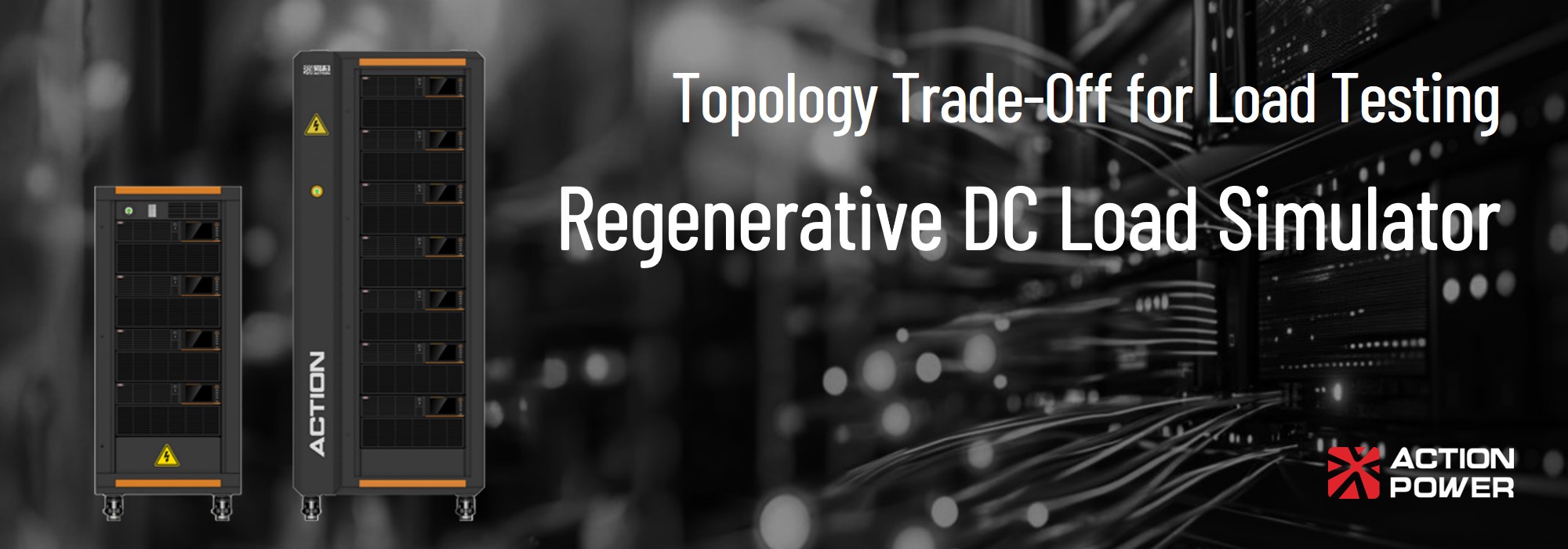
Conventional testing applications where programmable electronic loads are deployed used to see a definite trade-off between dynamic performance and the power efficiency of regenerative load functionality. This contradiction derives from the fact that each is grounded in fundamentally different power electronics topologies and architectures.
While test engineers might not be reluctant to implement a highly dynamic but energy-consuming conventional load when the EUT is at the component level with a relatively low power rating, this trade-off is now a critical concern in industries like AI infrastructure. In these applications, both dynamic response and power regeneration are essential, given the rapidly shifting power profiles of AI servers and their high-power operating conditions.
To have one’s cake and eat it too is no longer a negligible expectation; it is exactly what test engineers demand and what power electronic technologies must strive to achieve compatibility between high-dynamic performance and sustainable energy recovery. To better understand this contradiction, we start this blog by studying the technical foundations of linear and switch-mode programmable electronic loads, alongside their pros and cons. Following this, we will extend to how ActionPower India strikes the balance and breaks the boundary.
Topology and Architecture are Where Technically the Trade-Off Comes from When Deploying E-Loads
The exclusive trade-off between response speed and energy efficiency is not an engineering compromise born out of flawed design; rather, it is an inherently inevitable result of fundamental power electronic topologies.
Linear and switch-mode topologies, commonly accepted as the primary two approaches to building an electronic load, are both ultimately defined by how their architectures regulate current flow. Yet, they follow fundamentally different methodologies in dictating the operation of power semiconductors within the topology. One operates the device as a precise, variable resistor in a continuous state, while the other toggles rapidly between “fully ON” and “fully OFF” states using PWM.
It is precisely this distinct topological strategy in driving semiconductor components, such as MOSFETs or IGBTs, that draws the functional boundaries between linear and switch-mode loads.

Linear Load Mode Resembles a Continuous Operating and Adjustable Resistor
Programmable Loads architected on linear topology demonstrates high dynamics and fast response due to that power semiconductors typically like MOSFETs are deliberately biased to operate strictly within their active, or linear, region. [1]
While the transistors within this topology function as electronically controlled variable resistors that continuously dictate the exact drain current flowing through the device by regulating the gate voltage, the linear-mode architecture inherently demonstrates superior dynamic performance and rapid transient responses, given that its current regulation is continuous and smooth, allowing the system to entirely bypass the need for bulky passive filtering components.
However, since the semiconductors remain in a continuous state of conduction, the topology bears the full source voltage drop and conducts the full current during load test. Following the fundamental laws of thermodynamics [2], all absorbed electrical power is converted into Joule heating, expressed by the equation:
$$P_{dissipation} = V_{DS} \cdot I_D$$
where \(V_{DS}\) stands for the drain-to-source voltage and \(I_D\) is the absorbed drain current.
Since linear topology does not integrate any mechanism to invert DC back into AC, 100% of the absorbed energy is thus converted into heat which, in case of high-power scenarios, testing setup inevitably has to combine complex thermal management systems, such as forced-air or liquid cooling architectures, along with the electronic load.
Switch Mode Load Relies on PWM and is Functionally Limited by Switching Frequency though Energy Regenerative
In contrast to linear topologies which convert drawn power into complete heat waste, switch-mode architecture makes energy regeneration during load operation possible by forcing transistors to toggle exclusively between the saturation region (fully ON) and the cut-off region (fully OFF) at a designated switching frequency \(f_{sw}\), and consequently, by routing the power through a subordinate DC-AC inverter topology to return a considerable portion of the consumed energy back to the utility without causing thermal scalability issues.
Nevertheless, the fundamental fact that regenerative loads are realized through switch-mode topologies inherently imposes a bottleneck on dynamic performance, due to the objective physical limits of the switching operation itself rather than a design oversight. Hereby below are some downsides introduced by the switch-mode methodology:
LC Filters Supposed to Mitigate the Ripples from PWM Mathematically Restricts the Slew Rate (As a Key Specification of Dynamic Response)
The power recovery into the local utility should comply with the regional grid code with minimized harmonics that affect power system’s integrity, respective for the switch-mode topology it is usually installed with bulky LC (Inductor-Capacitor) in series at the output for such a purpose. Following Faraday’s law of induction [3]:
$$\frac{di}{dt} = \frac{\Delta V}{L}$$
A large \(L\) that represents inductance is essential for adequately flatten the ripple derived from the PWM operation. Correspondingly, the larger the \(L\) is, the more limited the rate of change of current \(\frac{di}{dt}\) is – respectively forcing a slower transient response, alternatively referred to the slew rate.
Bandwidth Limitations Tied to Switching Frequency That Undermine the Original Regenerative Intent
Nyquist sampling theorem [4] proposes a technical practice for stable closed-loop stability that the bandwidth of the control loop \(f_{bw}\) is ideally capped and restricted to one-tenth to one-fifth of the switching frequency \(f_{sw}\):
$$f_{bw} \approx \frac{1}{10} f_{sw}$$
A contradiction that lies here is that when scaling up with increased \(f_{sw}\) to enforce the system to operate with faster dynamics, power semiconductors typically such as traditional silicon IGBTs faces the inherent latency during turning on and off – a gap between cycles where a finite overlap period during which both high voltage and high current simultaneously exist across the device. The transient overlap generates a specific pulse of energy loss per cycle \(E_{sw}\). Consequently, the total switching power loss ($P_{sw}$) scales linearly with the switching frequency:
$$P_{sw} = (E_{on} + E_{off}) \cdot f_{sw}$$
Here comes the trap for test engineers, pushing traditional silicon devices to higher frequencies multiplies these transient heat pulses exponentially. The approach with the target of improving the response backfires as a worse thermal runaway or even causes catastrophic breakdown risks that the regenerative topology was originally designed to avoid.
Option-Based Compare and Comparison: ATLAS as Load vs. CORTEX DC as Load
To transition from theoretical topologies to practical engineering solutions, we can benchmark two flagship ActionPower India models: the ATLAS Series (representing cutting-edge linear load architecture) and the CORTEX DC Series (representing high-efficiency switch-mode regenerative architecture). By examining their 600V-class modules within an identical 3U rack space, the technological trade-offs we discussed earlier become distinctly quantifiable.
| Specification (3U / 600V Class) | ATLAS Series DC Load | CORTEX DC Series (as Load) |
|---|---|---|
| Core Architecture | Linear / Dissipative | Switch-mode / Regenerative |
| Max Power Density (per 3U) | Up to 6 kW | Up to 30 kW |
| Minimum Current Rise Time | 20 μs (Ultra-fast) | 500 μs ~ 1 ms |
| Energy Regeneration Rate | 0% (100% Heat Dissipation) | ~94% (Returned to Grid) |
| Ideal Testing Scenarios | AI Server Power, Nanosecond Transients | EV Battery Cycling, PV Inverters |
As illustrated by the data, the ATLAS Series sacrifices energy regeneration to achieve an ultra-fast 20μs current response and 500kHz transient sampling. It is the definitive choice for component-level testing where catching microsecond-level voltage drops – such as in AI server VRM modules – is paramount.
Conversely, the CORTEX DC Series excels in scalability and efficiency. By leveraging a regenerative switch-mode design, it packs up to five times the power (30kW) into the exact same 3U footprint and returns 94% of the drawn power back to the facility’s grid. This makes it the ultimate solution for megawatt-level EV battery and grid-tied inverter testing, where extreme dynamic speed is secondary to thermal management and energy cost savings.
ActionPower India’s Solutions of High-Dynamics Programmable Regenerative Load PRL
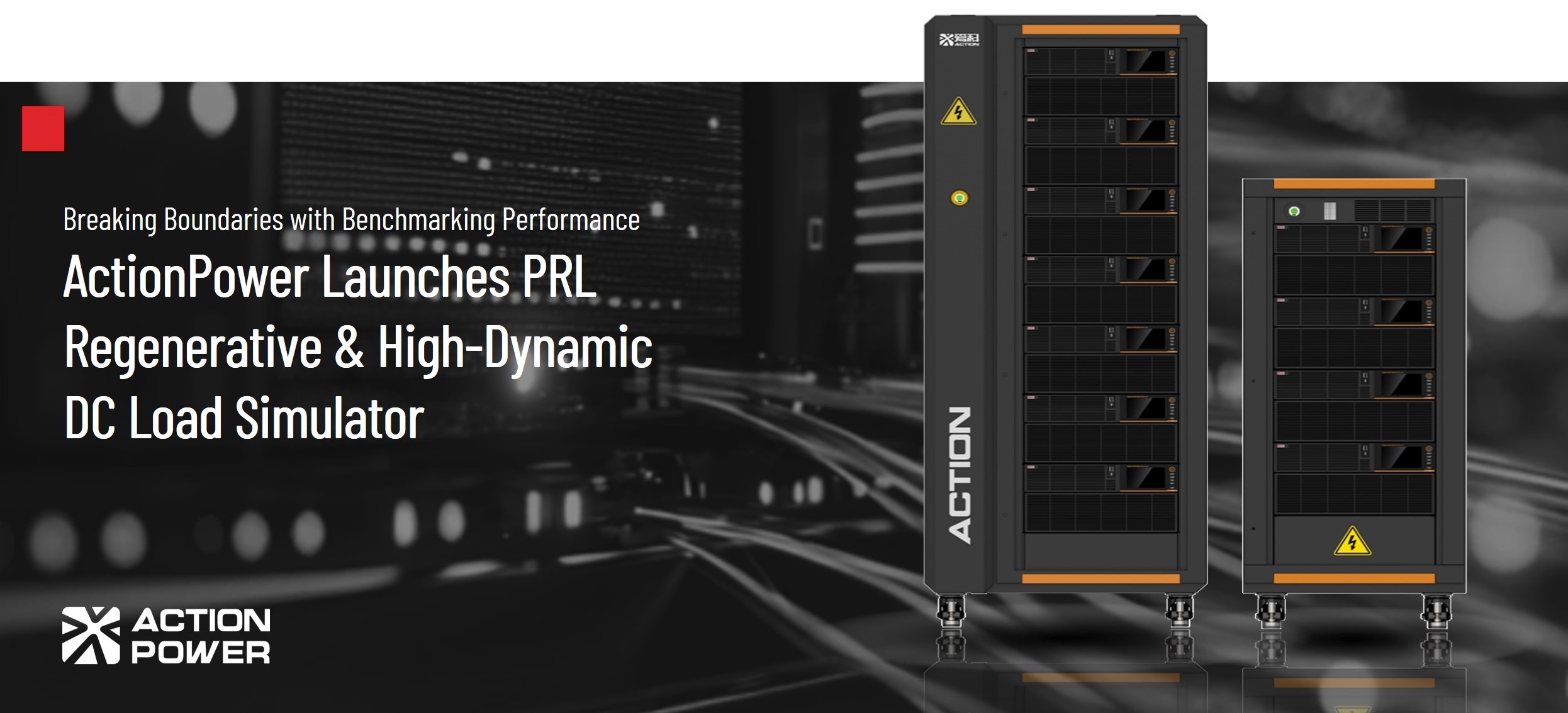
The PRL Series Regenerative Programmable DC Load is purposefully engineered to shatter the historical boundary between dynamic speed and regenerative efficiency. By reimagining power conversion controls from the ground up, ActionPower India delivers a proprietary “black-box” solution that achieves high-bandwidth transient responses alongside megawatt-level energy recovery.
- Uncompromised Slew Rates: Overcoming the sluggish response of typical regenerative systems, the PRL delivers extremely steep current transitions of up to 60 A/μs and microsecond-level rise times (≤6μs). PRL flawlessly tracks the aggressive power spikes demanded by AI server VRMs (50V/54V nodes) and EV traction drives (800V HVDC).
- Intelligent Transient Tracking: Driven by a high-speed processing platform, the system anticipates load variations to emulate complex profiles without lag, supporting dynamic testing frequencies up to 30kHz and an intense 1.6x transient overload for 2 milliseconds.
- Maximum Energy Viability: Despite its extreme dynamic agility, the PRL operates as a grid-tied regenerative load. PRL recovers up to 85% of the drawn electrical power back to the facility’s grid, virtually eliminating the catastrophic heat generation and massive cooling costs associated with conventional linear loads.
Explore more Technical Details about PRL
Talk with an Expert from ActionPower India for Your Load Emulation Testing Applications
Aligning the fundamental topology of your testing equipment with the physical realities of your Device Under Test (DUT) is critical to your engineering success.
Whether you require the nanosecond-level precision of the linear ATLAS Series, the megawatt scalability of the regenerative CORTEX DC Series, or the ultimate dynamic balance of the PRL Series, ActionPower India has the exact architecture to match your testing profiles.
Do not let equipment bottlenecks limit your engineering potential or inflate your energy costs. Reach out to our local engineering team in India today. Our application experts are ready to analyse your load requirements, discuss architectural trade-offs, and seamlessly integrate the optimal programmable load into your ATE environment.